EduNinja
[Maximum number: 3]

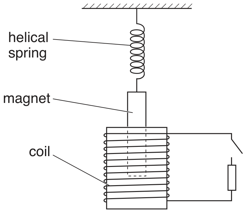
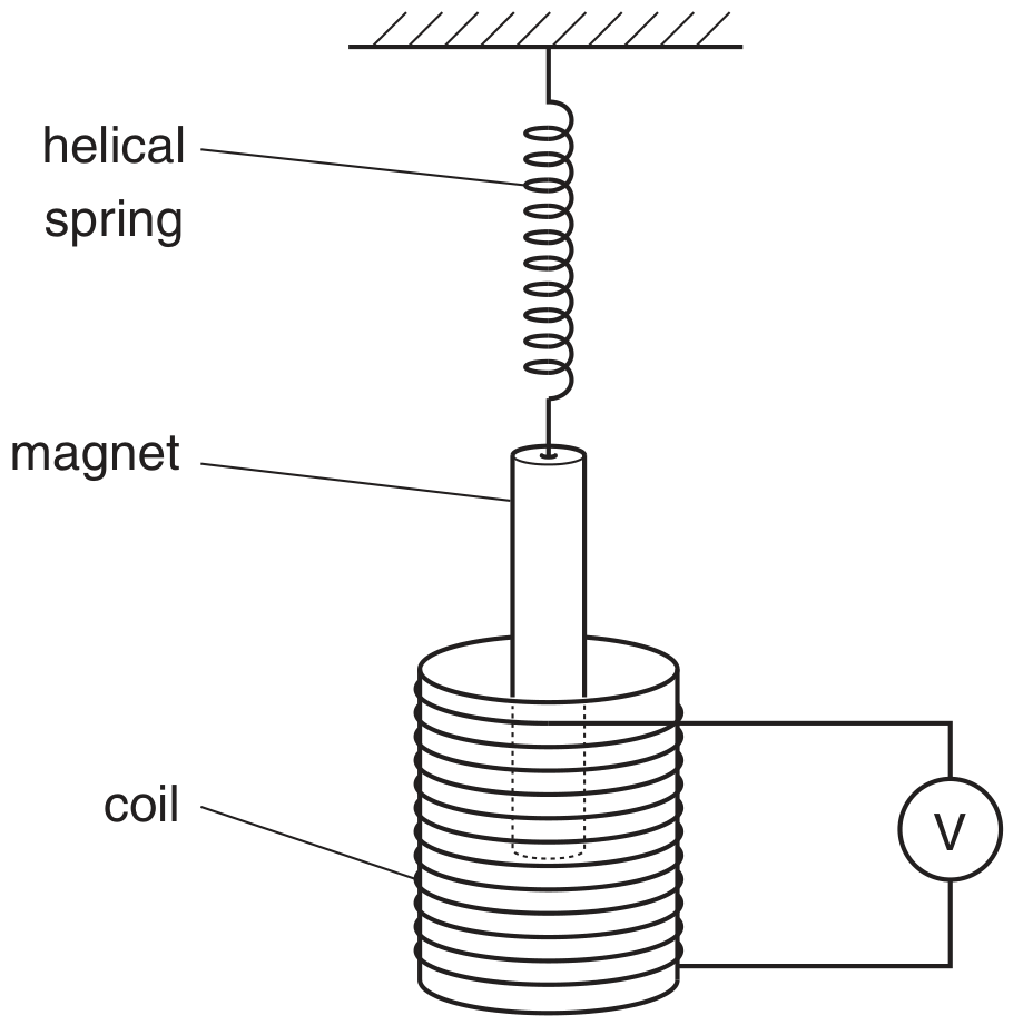
A light spring is suspended from a fixed point. A bar magnet is attached to the end of the spring, as shown in Fig. 1.1.
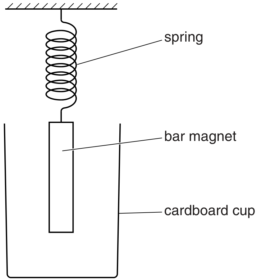
Fig. 1.1

Fig. 1.1

In order to shield the magnet from draughts, a cardboard cup is placed around the magnet but does not touch it.
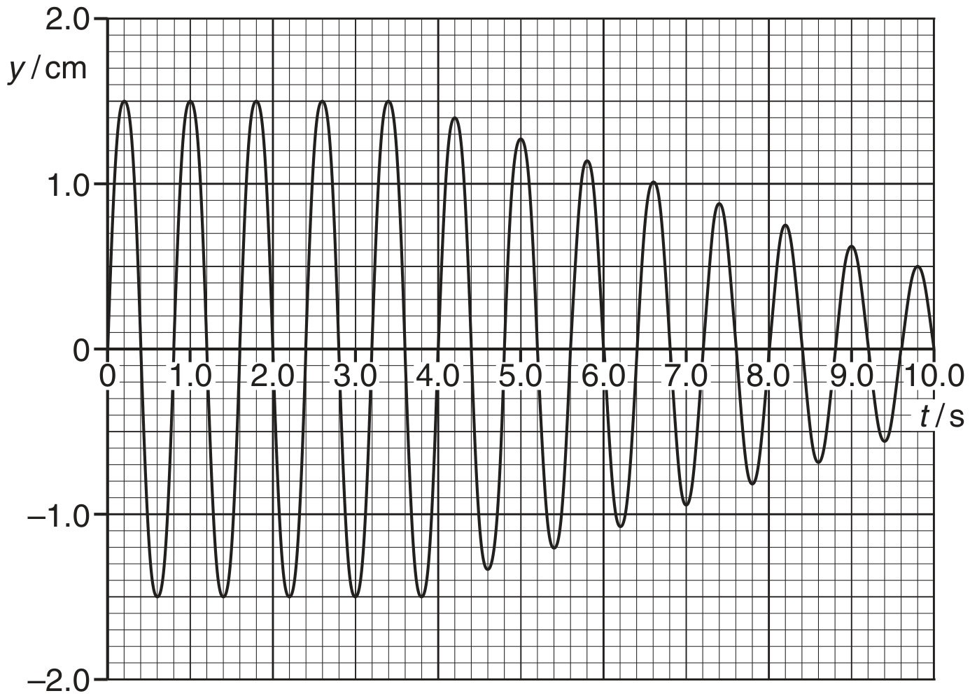
The magnet is displaced vertically and then released. The variation with time t of the vertical displacement y of the magnet is shown in Fig. 1.2.
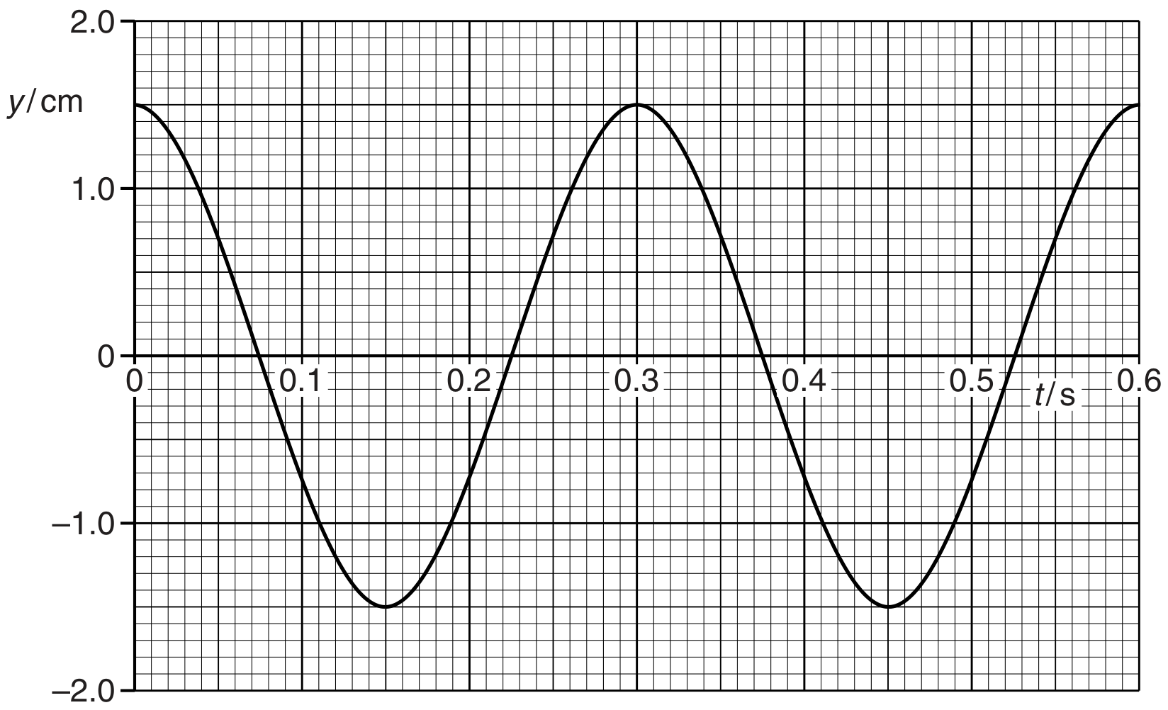
Fig. 1.2

Fig. 1.2

The mass of the magnet is 130 g .

(a)

The cardboard cup is now replaced with a cup made of aluminium foil. During 10 complete oscillations of the magnet, the amplitude of vibration is seen to decrease to 0.75 cm from that shown in Fig. 1.2. The change in angular frequency is negligible.

[ 3 ]
(i)

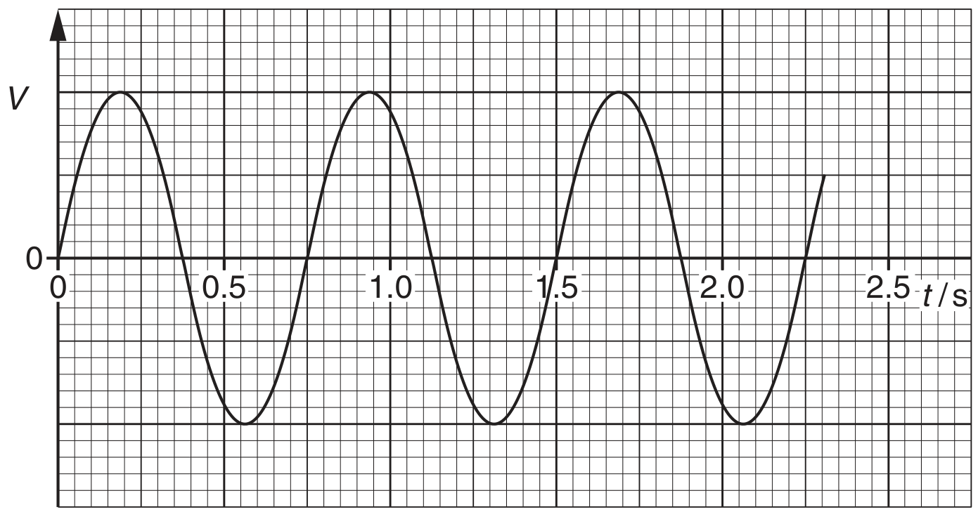
Use Faraday's law of electromagnetic induction to explain why the amplitude of the oscillations decreases.

[ 3 ]
[Maximum number: 6]

A bar magnet is suspended from the free end of a helical spring, as illustrated in Fig. 3.1.

Fig. 3.1

Fig. 3.1

One pole of the magnet is situated in a coil of wire. The coil is connected in series with a switch and a resistor. The switch is open.

The magnet is displaced vertically and then released. As the magnet passes through its rest position, a timer is started. The variation with time t of the vertical displacement y of the magnet from its rest position is shown in Fig. 3.2.

Fig. 3.2

Fig. 3.2

At time t=4.0 st=4.0 \mathrm{~s}, the switch is closed.

(a)
(i)

State Faraday's law of electromagnetic induction.

[ 2 ]
(ii)

Explain why, after time t=4.0 st=4.0 \mathrm{~s}, the amplitude of vibration of the magnet is seen to decrease.

[ 4 ]
[Maximum number: 3]

A bar magnet is suspended vertically from the free end of a helical spring, as shown in Fig. 5.1.

Fig. 5.1

Fig. 5.1

One pole of the magnet is situated in a coil. The coil is connected in series with a high-resistance voltmeter.
The magnet is displaced vertically and then released.
The variation with time t of the reading V of the voltmeter is shown in Fig. 5.2.

Fig. 5.2

Fig. 5.2

(a)
(i)

State Faraday's law of electromagnetic induction.

[ 2 ]
(ii)

Use Faraday's law to explain why
1. there is a reading on the voltmeter,
2. this reading varies in magnitude,
3. the reading has both positive and negative values.

[ 1 ]
[Maximum number: 2]

A Hall probe is placed a distance d from a long straight current-carrying wire, as illustrated in Fig.5.1.

Fig. 5.1

Fig. 5.1

The direct current in the wire is 4.0 A . Line XY is normal to the wire.
The Hall probe is rotated about the line X Y to the position where the reading VHV_{H} of the Hall probe is maximum.

(a)

A student suggests that the Hall probe in (a) is replaced with a small coil connected in series with a millivoltmeter. The constant current in the wire is 4.0 A .
In order to obtain data to plot a graph showing the variation with distance x of the magnetic flux density, the student suggests that readings of the millivoltmeter are taken when the coil is held in position at different values of x.

Comment on this suggestion.

[ 2 ]
(a)

State the relation between magnetic flux density B and magnetic flux Φ\Phi, explaining any other symbols you use.

(b)
(i)

State Faraday's law of electromagnetic induction.

[ 2 ]
(ii)

The Hall probe in (b) is replaced by a small flat coil of wire. The coil is moved at constant speed along the line XY . The plane of the coil is parallel to the faces of the poles of the magnet.

On the axes of Fig. 5.3, sketch a graph to show the variation with time t of the e.m.f. E induced in the coil.

Fig. 5.3

Fig. 5.3

[ 3 ]
(a)

A long solenoid has an area of cross-section of 28 cm228 \mathrm{~cm}^{2}, as shown in Fig. 5.1.

Fig. 5.1

Fig. 5.1

A coil C consisting of 160 turns of insulated wire is wound tightly around the centre of the solenoid.
The magnetic flux density B at the centre of the solenoid is given by the expression

B=μ0nIB=\mu_{0} n I

where I is the current in the solenoid, n is a constant equal to 1.5×10³ m11.5 \times 10^{3} \mathrm{~m}^{-1} and μ0\mu_{0} is the permeability of free space.

Calculate, for a current of 3.5 A in the solenoid,

[ 2 ]
(i)

the flux linkage in the coil C .
flux linkage = Wb

[ 2 ]
(b)
(i)

State Faraday's law of electromagnetic induction.

[ 2 ]
(ii)

The current in the solenoid in (b) is reversed in direction in a time of 0.80 s . Calculate the average e.m.f. induced in coil C.
e.m.f. = V

[ 2 ]
[Maximum number: 7]

A uniform magnetic field of flux density B makes an angle θ\theta with a flat plane PQRS , as shown in Fig. 5.1.

Fig. 5.1

Fig. 5.1

The plane PQRS has area A.

(a)

State

[ 1 ]
(i)

an expression, in terms of A, B and θ\theta, for the magnetic flux Φ\Phi through the plane PQRS.

[ 1 ]
(b)

A vertical aluminium window frame DEFG has width 52 cm and length 95 cm , as shown in Fig. 5.2.

Fig. 5.2

Fig. 5.2

The frame is hinged along the vertical edge DG.
The horizontal component BHB_{\mathrm{H}} of the Earth's magnetic field is 1.8×10⁵ T1.8 \times 10^{-5} \mathrm{~T}. For the closed window, the frame is normal to the horizontal component BHB_{\mathrm{H}}.
The window is opened so that the plane of the window rotates through 9090^{\circ}.

[ 3 ]
(i)

Explain why, when the window is opened, the change in magnetic flux linkage due to the vertical component of the Earth's magnetic field is zero.

[ 1 ]
(ii)

Calculate, for the window opening through an angle of 9090^{\circ}, the change in magnetic flux linkage.
change in flux linkage = Wb

[ 2 ]
(c)
(i)

State Faraday's law of electromagnetic induction.

[ 2 ]
(ii)

The window in (b) is opened in a time of 0.30 s . Use your answer in (b)(ii) to calculate the average e.m.f. induced in the window frame.
e.m.f. =

(iii)

State the sides of the window frame between which the e.m.f. is induced.
between side and side

[ 1 ]
[Maximum number: 5]

A solenoid is connected in series with a battery and a switch. A Hall probe is placed close to one end of the solenoid, as illustrated in Fig. 7.1.

Fig. 7.1

Fig. 7.1

The current in the solenoid is switched on. The Hall probe is adjusted in position to give the maximum reading. The current is then switched off.

(a)

The Hall probe is now replaced by a small coil. The plane of the coil is parallel to the end of the solenoid.

[ 5 ]
(i)

State Faraday's law of electromagnetic induction.

[ 2 ]
(ii)

On the axes of Fig. 7.3, sketch a graph to show the variation with time t of the e.m.f. E induced in the coil when the current in the solenoid is switched on and then switched off.

Fig. 7.3

Fig. 7.3

[ 3 ]
(a)

The Hall probe in (a) is now replaced with a small coil of wire connected to a sensitive voltmeter. The coil is arranged so that its plane is normal to the magnetic field of the wire.

[ 6 ]
(i)

State Faraday's law of electromagnetic induction and hence explain why the voltmeter indicates a zero reading.

[ 3 ]
(ii)

State three different ways in which an e.m.f. may be induced in the coil.
1.
2.

[ 3 ]
(a)

State Faraday's law of electromagnetic induction.

[ 2 ]
0