[Maximum number: 5]
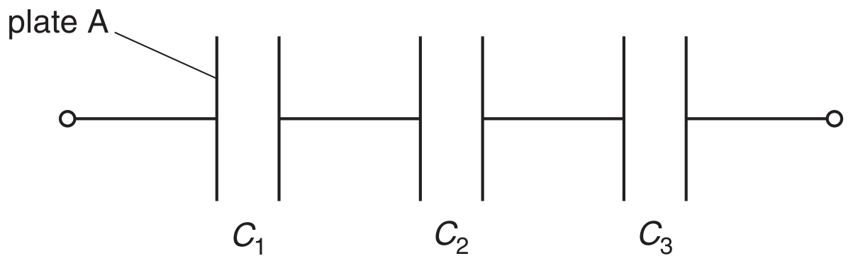
A capacitor consists of two metal plates separated by an insulator, as shown in Fig. 3.1.
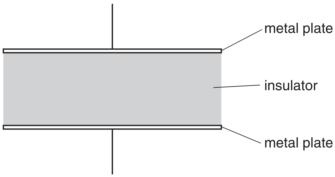
Fig. 3.1
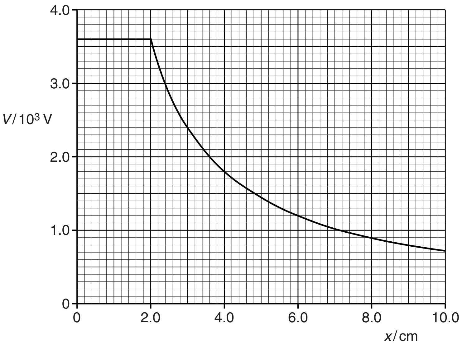
The potential difference between the plates is V. The variation with V of the magnitude of the charge Q on one plate is shown in Fig. 3.2.
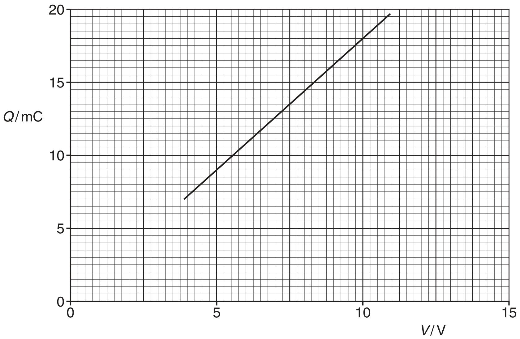
Fig. 3.2
(a)
Use Fig. 3.2 to determine
[ 2 ]
(i)
the capacitance of the capacitor,
capacitance =
[ 2 ]
(b)
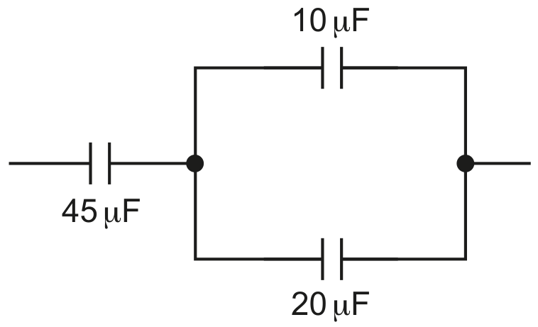
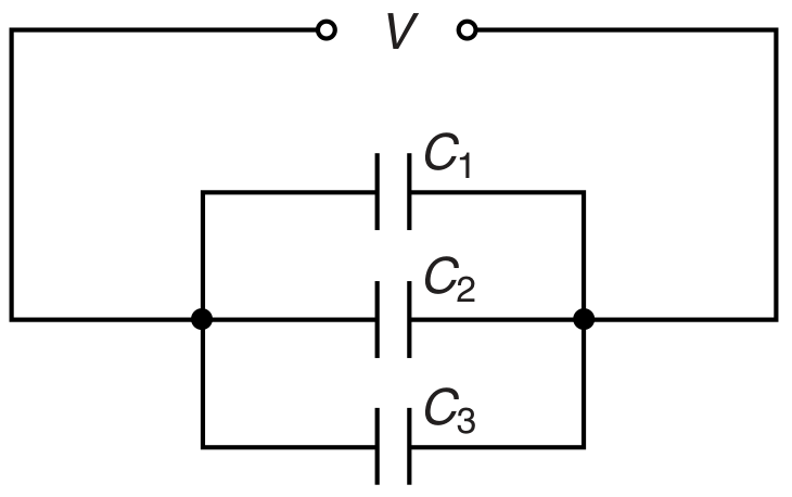
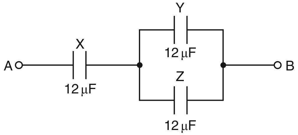
Three capacitors X, Y and Z , each of capacitance , are connected as shown in Fig. 3.3.
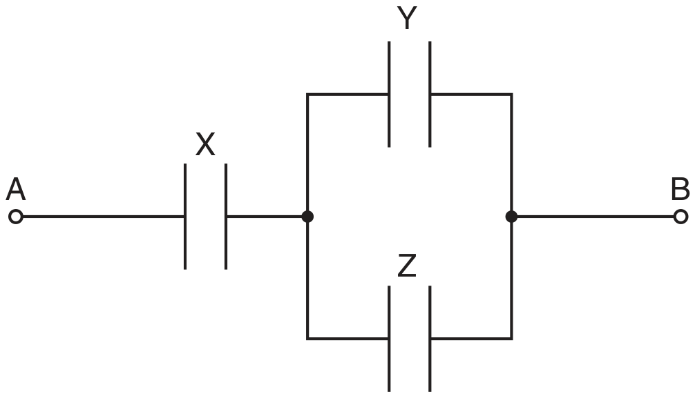
Fig. 3.3
Initially, the capacitors are uncharged.
A potential difference of 12 V is applied between points A and B .
Determine the magnitude of the charge on one plate of capacitor X.
charge =
[ 3 ]