EduNinja
(a)

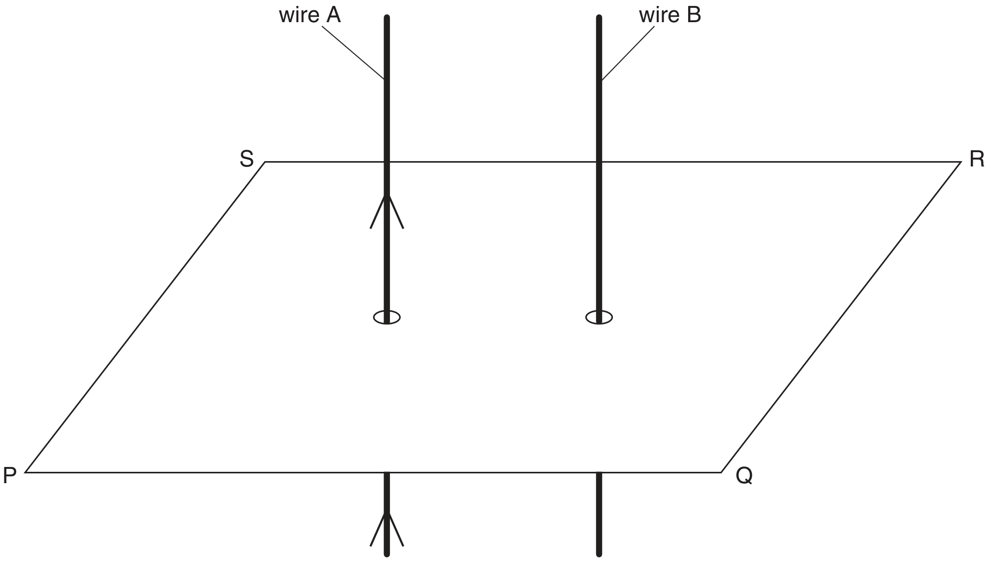
Two long straight vertical wires X and Y are separated by a distance of 4.5 cm , as illustrated in Fig. 5.1.
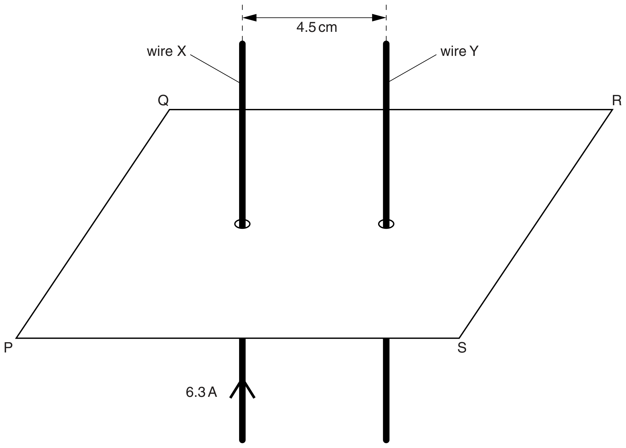
Fig. 5.1

Fig. 5.1

The wires pass through a horizontal card PQRS. The current in wire X is 6.3 A in the upward direction. Initially, there is no current in wire Y .

[ 3 ]
(i)

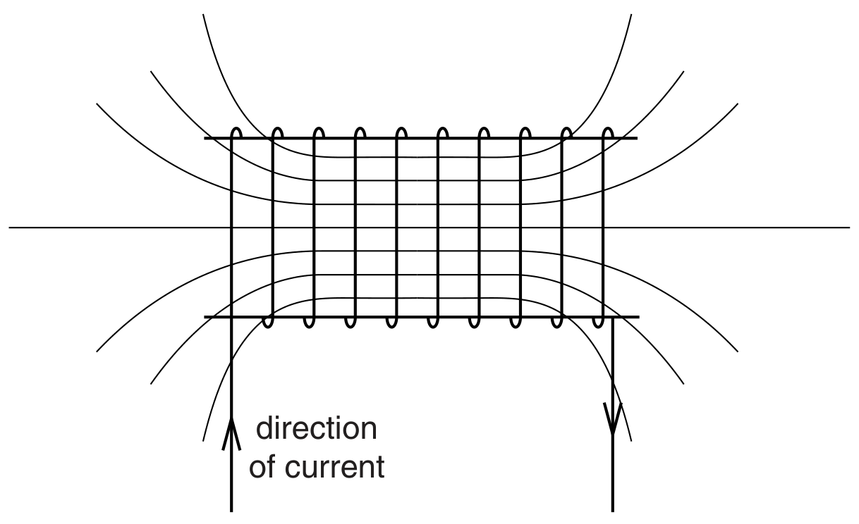
On Fig. 5.1, sketch, in the plane PQRS , the magnetic flux pattern due to the current in wire X. Show at least four flux lines.

[ 3 ]
(ii)

The magnetic flux density B at a distance x from a long straight current-carrying wire is given by the expression

B=μ0I2πxB=\frac{\mu_{0} I}{2 \pi x}

where I is the current in the wire and μ0\mu_{0} is the permeability of free space.
Calculate the magnetic flux density at wire Y due to the current in wire X .

flux density =
(b)

The currents in the two wires in (b)(iii) are not equal.

Explain whether the force per unit length on the two wires will be the same, or different.

[ 2 ]
[Maximum number: 2]

A Hall probe is placed a distance d from a long straight current-carrying wire, as illustrated in Fig.5.1.

Fig. 5.1

Fig. 5.1

The direct current in the wire is 4.0 A . Line XY is normal to the wire.
The Hall probe is rotated about the line X Y to the position where the reading VHV_{H} of the Hall probe is maximum.

(a)

The Hall probe is now moved away from the wire, along the line XY .

On the axes of Fig.5.2, sketch a graph to show the variation of the Hall voltage VHV_{\mathrm{H}} with distance x of the probe from the wire. Numerical values are not required on your sketch.

Fig. 5.2

Fig. 5.2

[ 2 ]
(a)

A long solenoid has an area of cross-section of 28 cm228 \mathrm{~cm}^{2}, as shown in Fig. 5.1.

Fig. 5.1

Fig. 5.1

A coil C consisting of 160 turns of insulated wire is wound tightly around the centre of the solenoid.
The magnetic flux density B at the centre of the solenoid is given by the expression

B=μ0nIB=\mu_{0} n I

where I is the current in the solenoid, n is a constant equal to 1.5×10³ m11.5 \times 10^{3} \mathrm{~m}^{-1} and μ0\mu_{0} is the permeability of free space.

Calculate, for a current of 3.5 A in the solenoid,

[ 2 ]
(i)

the magnetic flux density at the centre of the solenoid,
flux density = T

[ 2 ]
(a)

An incomplete diagram for the magnetic flux pattern due to a current-carrying solenoid is illustrated in Fig. 5.1.

Fig. 5.1

Fig. 5.1

[ 2 ]
(i)

On Fig. 5.1, draw arrows on the field lines to show the direction of the magnetic field.

[ 1 ]
(ii)

State the feature of Fig. 5.1 that indicates that the magnetic field strength at each end of the solenoid is less than that at the centre.

[ 1 ]
[Maximum number: 2]

A simple transformer is illustrated in Fig. 6.1.

Fig. 6.1

Fig. 6.1

(a)

State

[ 2 ]
(i)

why the iron core is laminated,

[ 2 ]
[Maximum number: 6]

Two long straight parallel copper wires A and B are clamped vertically. The wires pass through holes in a horizontal sheet of card PQRS, as shown in Fig. 7.1.

Fig. 7.1

Fig. 7.1

(a)

There is a current in wire A in the direction shown on Fig. 7.1.

On Fig. 7.1, draw four field lines in the plane PQRS to represent the magnetic field due to the current in wire A.

[ 3 ]
(b)

The direct currents in wires A and B are now replaced by sinusoidal alternating currents of equal peak values. The currents are in phase.
Describe the variation, if any, of the force experienced by wire B.

[ 3 ]
(a)

A metal spring rests on a smooth table. The turns of the spring are equally spaced. The ends of the spring are connected to a d.c. power supply, as shown in Fig. 6.5.

Fig. 6.5

Fig. 6.5

The spring is connected to the d.c. power supply using flexible leads. The spring is not under tension.

With reference to magnetic fields, describe and explain the change in the distance between the turns of the spring when the power supply is first switched on.

[ 3 ]
(a)

A simple transformer with a soft-iron core is illustrated in Fig. 7.1.

Fig. 7.1

Fig. 7.1

[ 2 ]
(i)

Explain why the core is
1. made of iron,
2. laminated.

[ 2 ]
(a)

A long air-cored solenoid is connected to a power supply, so that the solenoid creates a magnetic field. Fig. 6.1 shows a cross-section through the middle of the solenoid.

Fig. 6.1

Fig. 6.1

The direction of the magnetic field at point W is indicated by the arrow. Three other points are labelled X, Y and Z .

[ 5 ]
(i)

On Fig. 6.1, draw arrows to indicate the direction of the magnetic field at each of the points X, Y and Z .

[ 3 ]
(ii)

Compare the magnitude of the flux density of the magnetic field:
- at X and at W
- at Y and at Z .

[ 2 ]
(b)

Two long parallel current-carrying wires are placed near to each other in a vacuum.

Explain why these wires exert a magnetic force on each other. You may draw a labelled diagram if you wish.

[ 3 ]
[Maximum number: 1]

A simple iron-cored transformer is illustrated in Fig. 6.1.

Fig. 6.1

Fig. 6.1

(a)
(i)

State why the primary and secondary coils are wound on a core made of iron.

[ 1 ]
0