EduNinja
[Maximum number: 5]

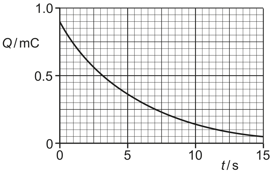
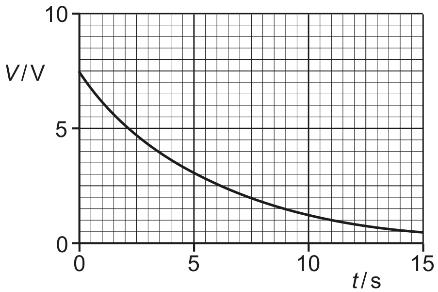
The variation with potential difference V of the charge Q on one of the plates of a capacitor is shown in Fig. 5.1.
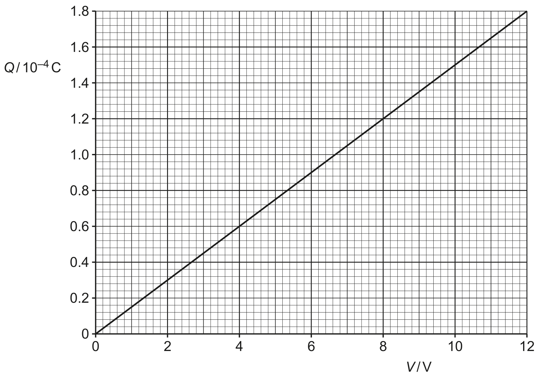
Fig. 5.1

Fig. 5.1

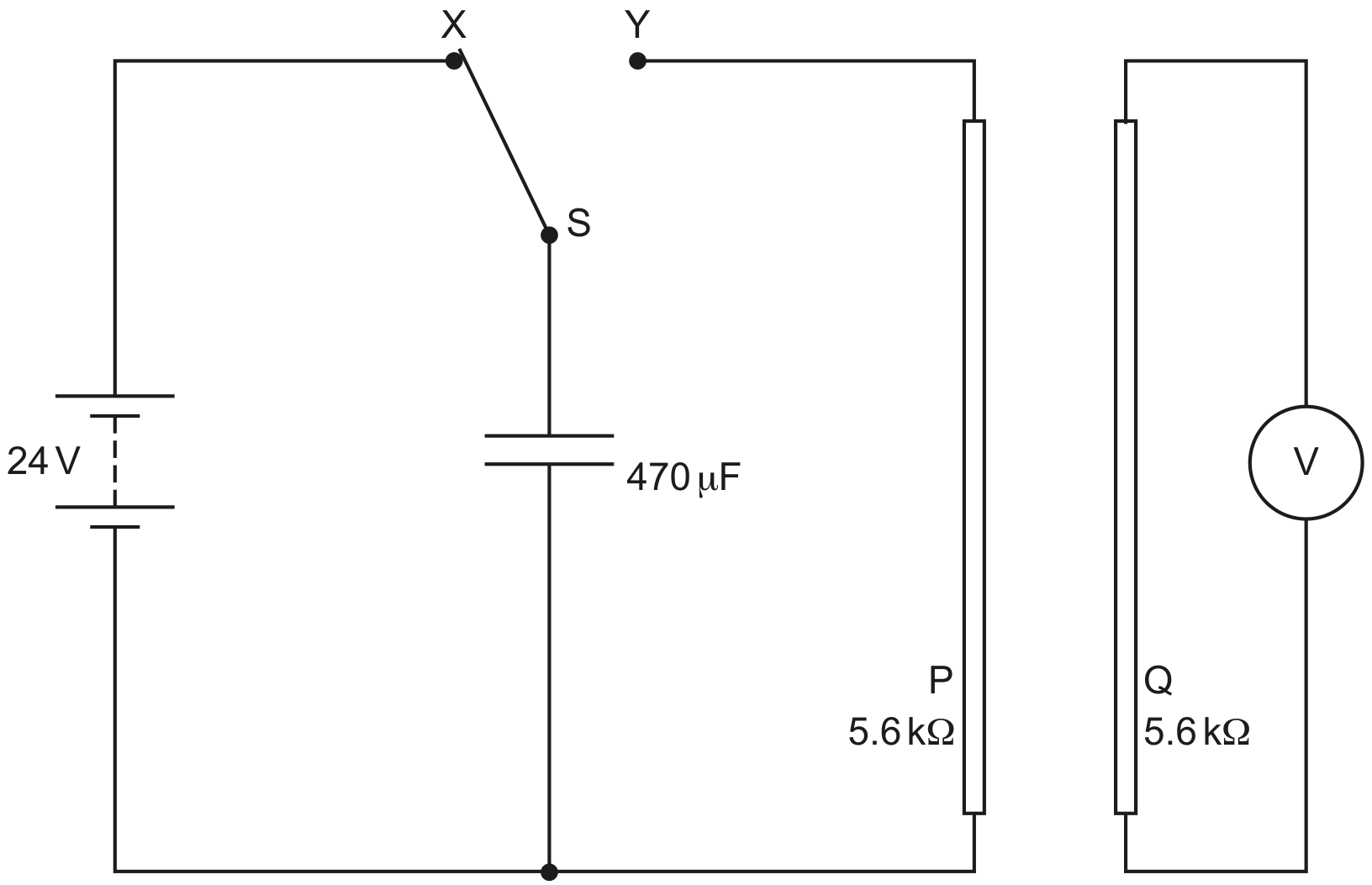
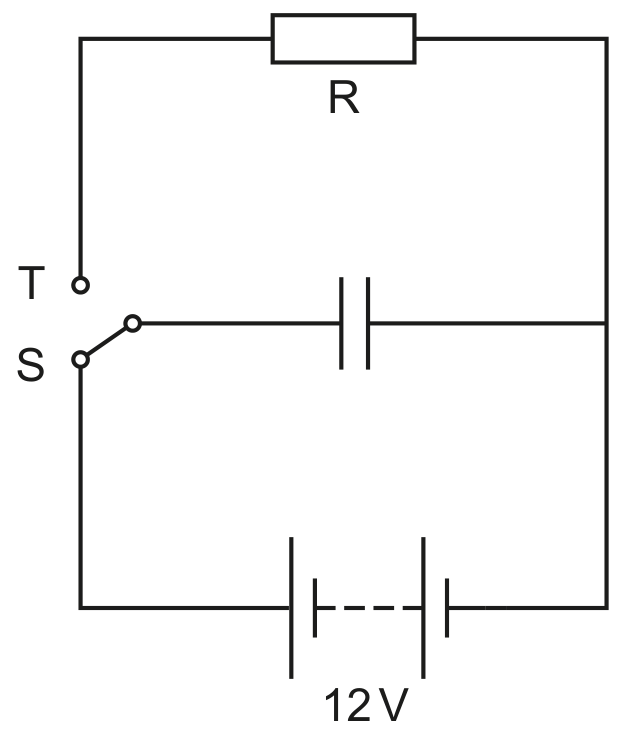
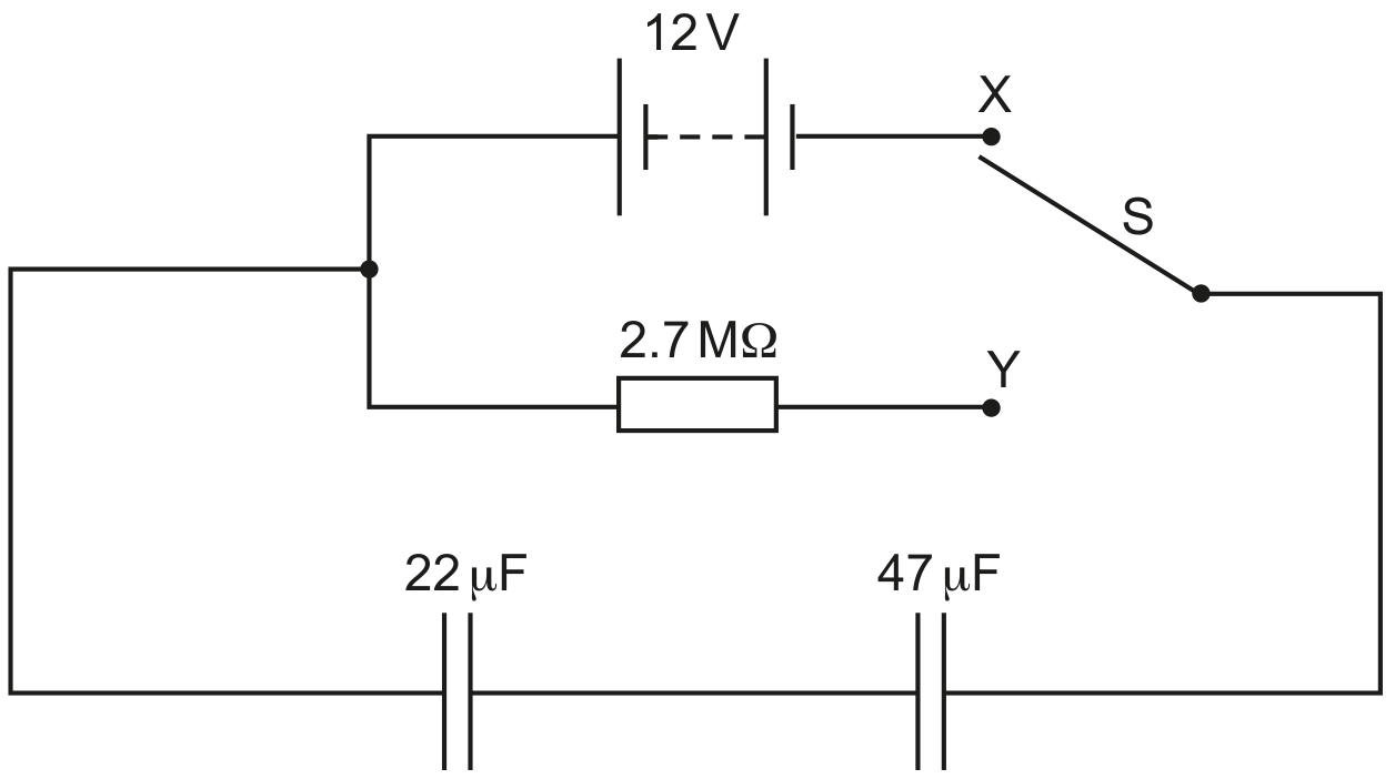
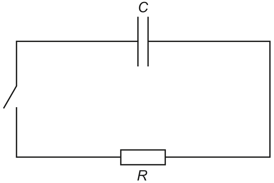
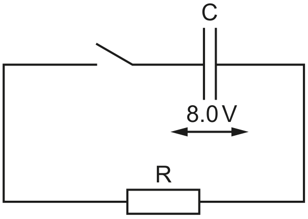
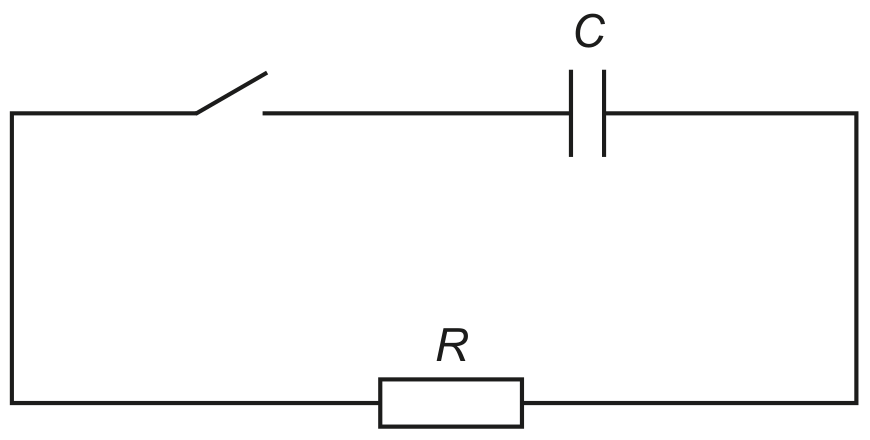
The capacitor is connected to an 8.0 V power supply and two resistors R and S as shown in Fig. 5.2.
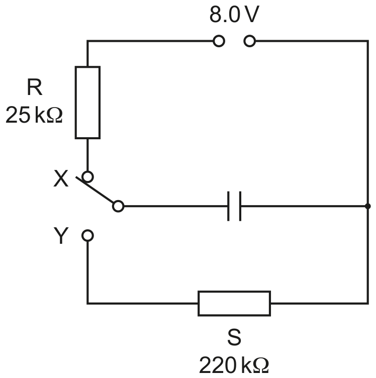
Fig. 5.2

Fig. 5.2

The resistance of R is 25kΩ25 \mathrm{k} \Omega and the resistance of S is 220kΩ220 \mathrm{k} \Omega.
The switch can be in either position X or position Y .

(a)

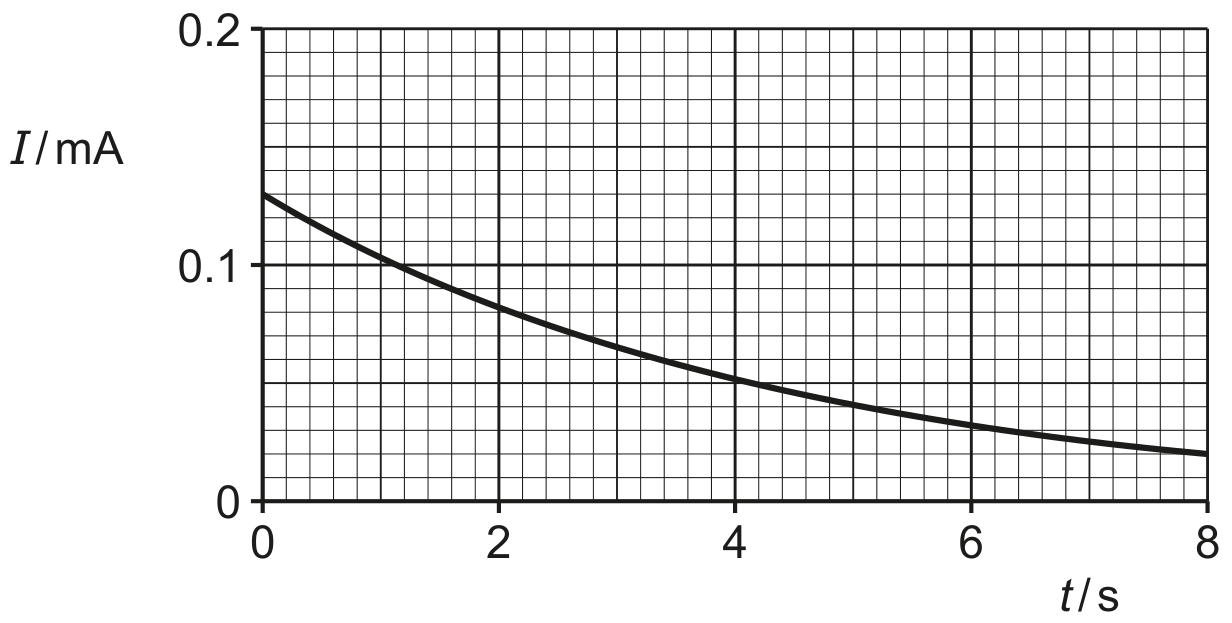
The switch is now moved to position Y.

[ 5 ]
(i)

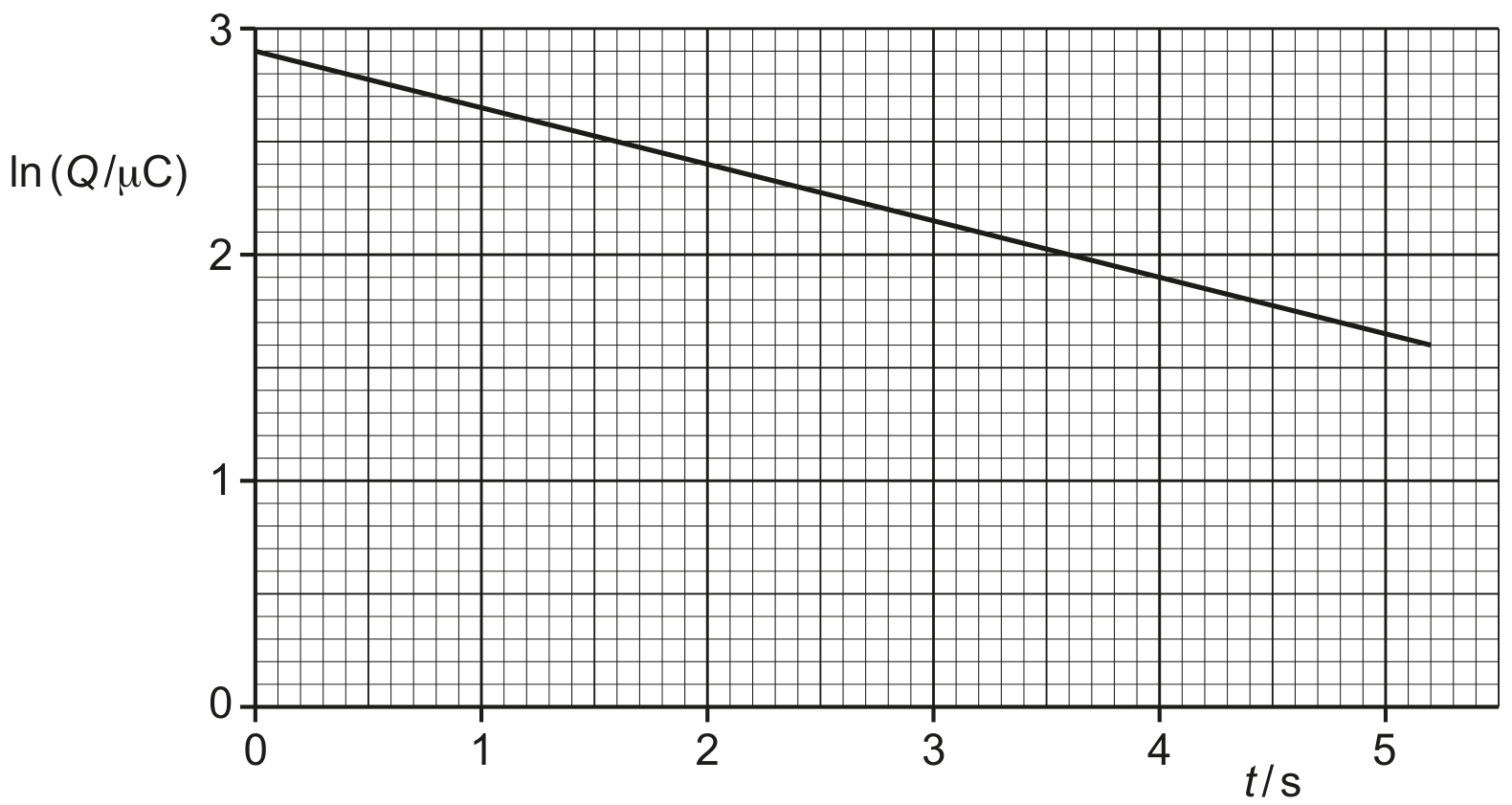
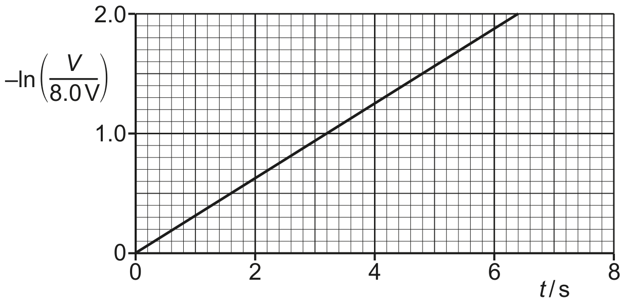
Show that the time constant of the discharge circuit is 3.3 s .

[ 2 ]
(ii)

The fully charged capacitor in (a) stores energy E.

Determine the time t taken for the stored energy to decrease from E to E / 9.

t=
[ 3 ]
[Maximum number: 3]

A capacitor of capacitance 470μ F470 \mu \mathrm{~F} is connected to a battery of electromotive force (e.m.f.) 24 V in the circuit of Fig. 5.1.

Fig. 5.1

Fig. 5.1

The two-way switch S is initially at position X.
P and Q are identical long straight wires, each with a resistance of 5.6kΩ5.6 \mathrm{k} \Omega. These wires are placed near to, and parallel to, each other. Wire Q is connected to a voltmeter.

At time t=0, switch S is moved to position Y so that the capacitor discharges through wire P .

(a)
(i)

Calculate the time constant τ\tau of the discharge circuit.

τ=\tau=
[ 1 ]
(ii)

On Fig. 5.2, sketch a line to show the variation with t of the current I in wire P as the capacitor discharges.

Fig. 5.2

Fig. 5.2

[ 2 ]
[Maximum number: 5]

A capacitor, a battery of electromotive force (e.m.f.) 12 V , a resistor R and a two-way switch are connected in the circuit shown in Fig. 5.1.

Fig. 5.1

Fig. 5.1

The switch is initially in position S . When the capacitor is fully charged, the switch is moved to position T so that the capacitor discharges. At time t after the switch is moved the charge on the capacitor is Q.

The variation with t of ln(Q/μC)\ln (Q / \mu C) is shown in Fig. 5.2.

Fig. 5.2

Fig. 5.2

(a)

Show that the capacitance of the capacitor is 1.5μ F1.5 \mu \mathrm{~F}.

[ 3 ]
(b)

Determine the resistance of R.

resistance =
(c)

A second identical resistor is now connected in parallel with R.

The switch is initially in position S . When the capacitor is fully charged, the switch is moved to position T so that the capacitor discharges. At time t after the switch is moved the charge on the capacitor is Q.

On Fig. 5.2, sketch a line to show the variation of ln(Q/μC)\ln (Q / \mu \mathrm{C}) with t between time t=0 and time t=5.0 st=5.0 \mathrm{~s}.

[ 2 ]
(a)

Two capacitors of capacitances 22μ F22 \mu \mathrm{~F} and 47μ F47 \mu \mathrm{~F}, and a resistor of resistance 2.7MΩ2.7 \mathrm{M} \Omega, are connected into the circuit of Fig. 5.2.

Fig. 5.2

Fig. 5.2

The battery has an e.m.f. of 12 V .

[ 3 ]
(i)

The two-way switch is now moved to position Y .

Determine the time taken for the potential difference (p.d.) across the 22μ F22 \mu \mathrm{~F} capacitor to become 6.0 V .

time =
[ 3 ]
[Maximum number: 6]

A capacitor of capacitance C and a resistor of resistance R are connected as shown in Fig. 6.1.

Fig. 6.1

Fig. 6.1

Initially, the capacitor is charged and the switch is open.

The switch is closed at time t=0.
Fig. 6.2 and Fig. 6.3 show, respectively, the variations with t of the charge Q on the capacitor and the potential difference (p.d.) V across the resistor.

Fig. 6.2

Fig. 6.2

Fig. 6.3

Fig. 6.3

(a)

Explain the shape of the line in Fig. 6.3 representing the variation of V with t.

[ 3 ]
(b)

Use Fig. 6.2 to show that the time constant of the circuit in Fig. 6.1 is 5.5 s .

[ 3 ]
[Maximum number: 4]

Part of an electric circuit is shown in Fig. 5.1.

Fig. 5.1

Fig. 5.1

The circuit is used to produce half-wave rectification of an alternating voltage of potential difference (p.d.) VIN V_{\text {IN }}.

The output p.d. across the 14kΩ14 \mathrm{k} \Omega resistor is VOUT V_{\text {OUT }}.

(a)

Fig. 5.2 shows the variation with time t of VIN V_{\text {IN }}.

Fig. 5.2

Fig. 5.2

Fig. 5.3 shows the variation with t of VOUT V_{\text {OUT }}.

Fig. 5.3

Fig. 5.3

[ 4 ]
(i)

Show that the time constant τ\tau for the discharge of the capacitor through the resistor is 0.038 s .

[ 2 ]
(ii)

Calculate the capacitance of C. Give a unit with your answer.
capacitance = unit

[ 2 ]
[Maximum number: 3]

A capacitor C is charged so that the potential difference (p.d.) V across its terminals is 8.0 V . The capacitor is connected into the circuit of Fig. 6.1.

Fig. 6.1

Fig. 6.1

The switch is initially open. The switch is closed at time t=0.

(a)

Fig. 6.3 shows the variation with t of ln(V8.0 V)-\ln \left(\frac{V}{8.0 \mathrm{~V}}\right).

Fig. 6.3

Fig. 6.3

[ 3 ]
(i)

Show that, when t is equal to one time constant, the value of ln(V8.0 V)-\ln \left(\frac{V}{8.0 \mathrm{~V}}\right) is equal to 1.0 .

[ 2 ]
(ii)

Determine the time constant τ\tau of the circuit in Fig. 6.1.

τ=\tau=
[ 1 ]
(iii)

Calculate the resistance of resistor R.
resistance = Ω\Omega

[Maximum number: 10]

Fig. 6.1 shows a capacitor of capacitance C connected in series with a resistor of resistance R.

Fig. 6.1

Fig. 6.1

Initially the switch is open and there is a p.d. of 12 V across the capacitor.
At time t=0, the switch is closed so that there is a current I in the resistor.
Fig. 6.2 shows the variation of I with t.

Fig. 6.2

Fig. 6.2

(a)

Explain the shape of the line in Fig. 6.2.

[ 3 ]
(b)

Use Fig. 6.2 to determine:

[ 5 ]
(i)

resistance R

R=Ω [2] \begin{aligned} & R= \\ & \Omega \text { [2] } \end{aligned}
[ 2 ]
(ii)

the time constant τ\tau of the circuit in Fig. 6.1.

τ= s [3] \begin{aligned} & \tau= \\ & \text { s [3] } \end{aligned}
[ 3 ]
(c)

Use your answers in (b) to determine capacitance C.

C =F [2]
[ 2 ]
0