EduNinja

A light spring is suspended from a fixed point. A bar magnet is attached to the end of the spring, as shown in Fig. 1.1.
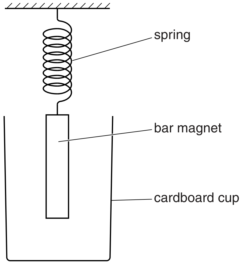
Fig. 1.1

Fig. 1.1

In order to shield the magnet from draughts, a cardboard cup is placed around the magnet but does not touch it.
The magnet is displaced vertically and then released. The variation with time t of the vertical displacement y of the magnet is shown in Fig. 1.2.
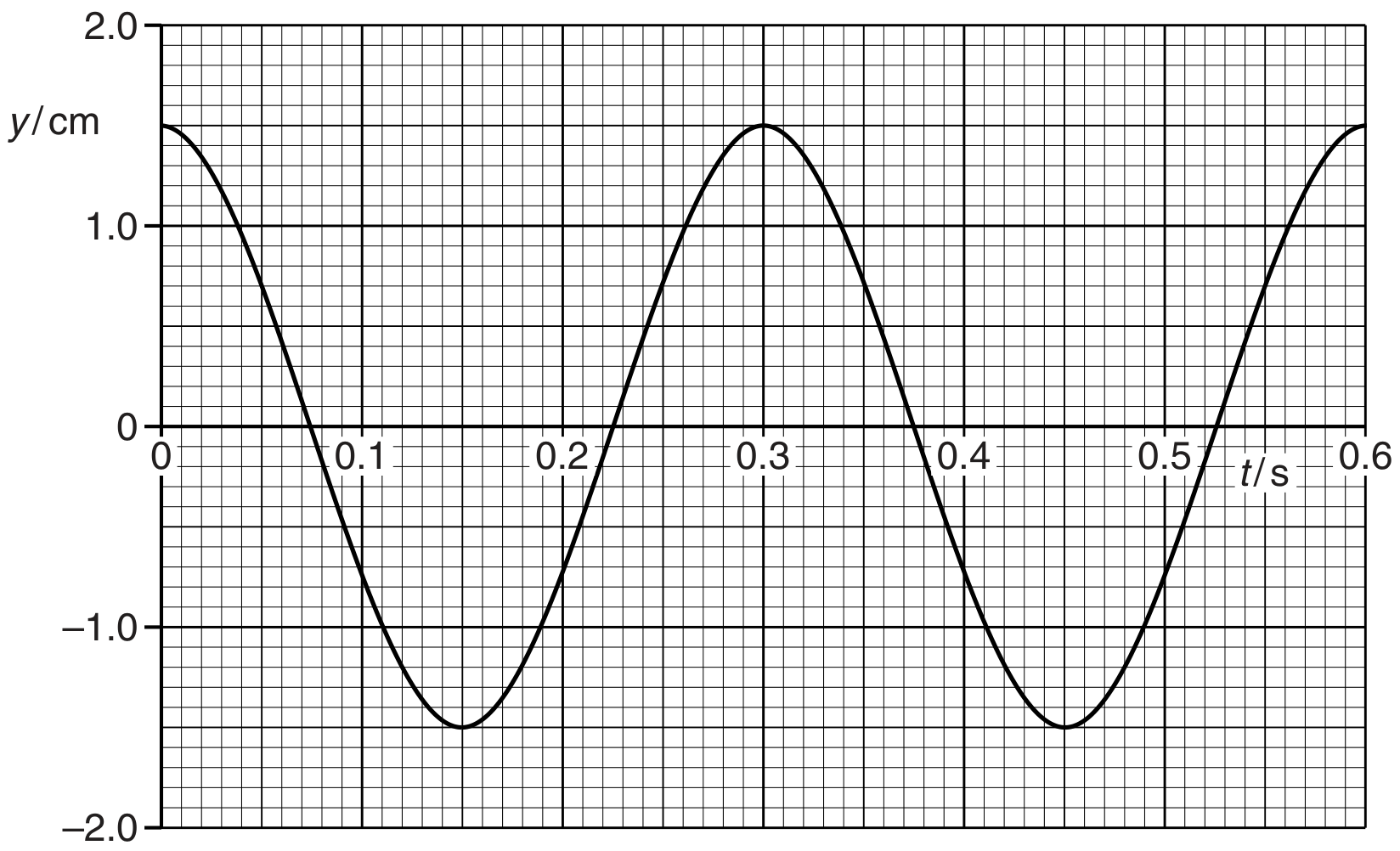
Fig. 1.2

Fig. 1.2

The mass of the magnet is 130 g .

(a)

The mass of the aluminium cup in (b) is 6.2 g . The specific heat capacity of aluminium is 910Jkg1 K1910 \mathrm{Jkg}^{-1} \mathrm{~K}^{-1}.
The energy in (b)(ii) is transferred to the cup as thermal energy. Calculate the mean rise in temperature of the cup.
temperature rise =

Please turn over for Question 2.

[Maximum number: 15]

Fig. 1.1 shows a small solid metal cylinder of mass m, length L and diameter d.

Fig. 1.1

Fig. 1.1

The cylinder is heated to a uniform temperature. The cylinder is then removed from the heat source and the cylinder is wrapped in an insulating material.

The temperature of the room is TRT_{\mathrm{R}}. At time t after the cylinder starts to cool, the surface temperature of the cylinder is TCT_{\mathrm{C}}.

It is suggested that TCT_{\mathrm{C}} is related to t by the relationship

(TCTR)=ZeUAtmc\left(T_{\mathrm{C}}-T_{\mathrm{R}}\right)=Z \mathrm{e}^{-\frac{U A t}{m c}}

where A is the total surface area of the cylinder, c is the specific heat capacity of the metal, and U and Z are constants.
Plan a laboratory experiment to test the relationship between TCT_{\mathrm{C}} and t.
Draw a diagram showing the arrangement of your equipment.
Explain how the results could be used to determine values for U and Z.
In your plan you should include:
- the procedure to be followed
- the measurements to be taken
- the control of variables
- the analysis of the data
- any safety precautions to be taken.
Diagram

(a)

A fixed mass of an ideal gas at a temperature of 20C20^{\circ} \mathrm{C} is sealed in a cylinder by a piston, as shown in Fig. 2.1.

Fig. 2.1

Fig. 2.1

The initial volume of the gas is 1.24×10⁴ m31.24 \times 10^{-4} \mathrm{~m}^{3}.
Thermal energy is supplied to the gas and its volume increases by 5.20×10⁵ m35.20 \times 10^{-5} \mathrm{~m}^{3}.

[ 3 ]
(i)

The mass of the gas is 16 g . For this expansion, there is a net transfer of 960 J of thermal energy to the gas.

Calculate the specific heat capacity c of the gas at this pressure.

c=..Jkg1 K1c=\ldots \ldots \ldots \ldots \ldots \ldots \ldots \ldots \ldots \ldots \ldots \ldots \ldots . . \mathrm{Jkg}^{-1} \mathrm{~K}^{-1}
[ 3 ]
(a)

The mass of nitrogen gas in another container is 24.0 g at a temperature of 27C27^{\circ} \mathrm{C}. The gas is cooled to its boiling point of 196C-196^{\circ} \mathrm{C}. Assume all the gas condenses to a liquid.

For this change the specific heat capacity of nitrogen gas is 1.04 kJ kg1 K11.04 \mathrm{~kJ} \mathrm{~kg}^{-1} \mathrm{~K}^{-1}.
The specific latent heat of vaporisation of nitrogen is 199 kJ kg1199 \mathrm{~kJ} \mathrm{~kg}^{-1}.
Determine the thermal energy, in kJ , removed from the nitrogen gas.
energy = kJ

[ 3 ]
(a)

Define specific heat capacity.

[ 2 ]
(b)

Use the information in (b) to suggest, with a reason, how the average specific heat capacity of water between 8C8^{\circ} \mathrm{C} and 16C16^{\circ} \mathrm{C} compares with its average value between 0C0^{\circ} \mathrm{C} and 8C8^{\circ} \mathrm{C}.

[ 1 ]
(a)

Define specific heat capacity.

[ 2 ]
(b)

An ideal gas of mass 0.35 kg is heated at a constant pressure of 2.0×10⁵ Pa2.0 \times 10^{5} \mathrm{~Pa} so that its internal energy increases by 7600 J . During this process, the volume of the gas increases from 0.038 m30.038 \mathrm{~m}^{3} to 0.063 m30.063 \mathrm{~m}^{3} and the temperature increases by 56C56^{\circ} \mathrm{C}.

(i)

Calculate the specific heat capacity of the gas for this process. Give a unit with your answer.
specific heat capacity = unit

(a)

Define specific latent heat.

[ 2 ]
(b)

A beaker containing a liquid is placed on a balance, as shown in Fig. 3.1.

Fig. 3.1

Fig. 3.1

A heater of power 110 W is immersed in the liquid. The heater is switched on and, when the liquid is boiling, balance readings m are taken at corresponding times t.

A graph of the variation with time t of the balance reading m is shown in Fig. 3.2.

Fig. 3.2

Fig. 3.2

[ 6 ]
(i)

State the feature of Fig. 3.2 which suggests that the liquid is boiling at a steady rate.

[ 1 ]
(ii)

Use data from Fig. 3.2 to determine a value for the specific latent heat L of vaporisation of the liquid.

L=Jkg1 [3] \begin{aligned} & L= \\ & \mathrm{Jkg}^{-1} \text { [3] } \end{aligned}
[ 3 ]
(iii)

State, with a reason, whether the value determined in (ii) is likely to be an overestimate or an underestimate of the normally accepted value for the specific latent heat of vaporisation of the liquid.

[ 2 ]
(a)

Define specific latent heat.

[ 2 ]
(b)

An electrical heater is immersed in some melting ice that is contained in a funnel, as shown in Fig. 3.1.

Fig. 3.1

Fig. 3.1

The heater is switched on and, when the ice is melting at a constant rate, the mass m of ice melted in 5.0 minutes is noted, together with the power P of the heater. The power P of the heater is then increased. A new reading for the mass m of ice melted in 5.0 minutes is recorded when the ice is melting at a constant rate.

Data for the power P and the mass m are shown in Fig. 3.2.

Fig. 3.2

Fig. 3.2

[ 2 ]
(i)

Complete Fig. 3.2 to determine the mass melted per second for each power of the heater.

[ 2 ]
(ii)

Use the data in the completed Fig. 3.2 to determine

(a)

Define specific latent heat.

[ 2 ]
(b)

The heater in an electric kettle has a power of 2.40 kW .

When the water in the kettle is boiling at a steady rate, the mass of water evaporated in 2.0 minutes is 106 g .

The specific latent heat of vaporisation of water is 2260Jg12260 \mathrm{Jg}^{-1}.
Calculate the rate of loss of thermal energy to the surroundings of the kettle during the boiling process.
rate of loss = W

[ 3 ]
(a)

An electric water heater contains a tube through which water flows at a constant rate. The water in the tube passes over a heating coil, as shown in Fig. 3.1.

Fig. 3.1

Fig. 3.1

The water flows into the tube at a temperature of 18C18^{\circ} \mathrm{C}. When the power of the heater is 3.8 kW , the temperature of the water at the outlet is 42C42^{\circ} \mathrm{C}.

The specific heat capacity of water is 4.2Jg1 K14.2 \mathrm{Jg}^{-1} \mathrm{~K}^{-1}.

[ 5 ]
(i)

Use the data to calculate the flow rate, in gs1\mathrm{gs}^{-1}, of water through the tube.
flow rate = gs1\mathrm{gs}^{-1}

[ 3 ]
(ii)

State and explain whether your answer in (i) is likely to be an overestimate or an underestimate of the flow rate.

[ 2 ]
0