EduNinja
[Maximum number: 2]

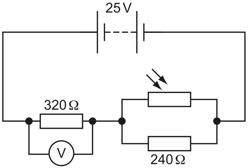
A battery of electromotive force 12 V and negligible internal resistance is connected to two resistors and a light-dependent resistor (LDR), as shown in Fig. 4.1.
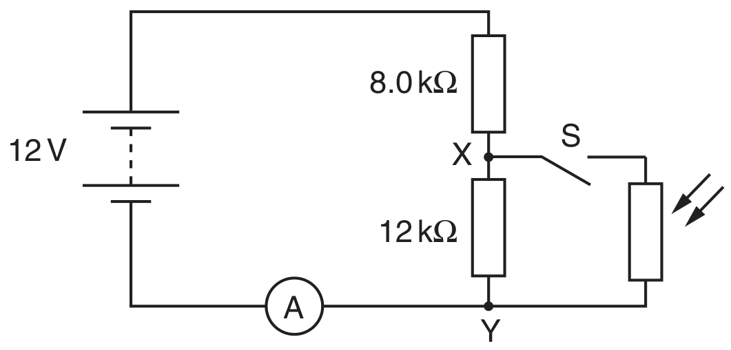
Fig. 4.1

Fig. 4.1

An ammeter is connected in series with the battery. The LDR and switch S are connected across the points XY .

(a)

The switch S is open. Calculate the potential difference (p.d.) across X Y.

 p. d. =\text { p. d. }=
(b)

The switch S remains closed. The intensity of the light on the LDR is increased. State and explain the change to

[ 2 ]
(i)

the p.d. across XY .

[ 2 ]

Fig. 5.1 shows a 12 V power supply with negligible internal resistance connected to a uniform metal wire AB . The wire has length 1.00 m and resistance 10Ω10 \Omega. Two resistors of resistance 4.0Ω4.0 \Omega and 2.0Ω2.0 \Omega are connected in series across the wire.

Fig. 5.1

Fig. 5.1

Currents I1,I2I_{1}, I_{2} and I3I_{3} in the circuit are as shown in Fig. 5.1.

(a)

Calculate the potential difference (p.d.) between the points C and D , as shown in Fig. 5.1. The distance A C is 40 cm and D is the point between the two series resistors.

[Maximum number: 2]

A uniform resistance wire A B has length 50 cm and diameter 0.36 mm . The resistivity of the metal of the wire is 5.1×10⁷Ω m5.1 \times 10^{-7} \Omega \mathrm{~m}.

(a)

The wire A B is connected in series with a power supply E and a resistor R as shown in Fig. 5.1.

Fig. 5.1

Fig. 5.1

The electromotive force (e.m.f.) of E is 6.0 V and its internal resistance is negligible. The resistance of R is 2.5Ω2.5 \Omega. A second uniform wire C D is connected across the terminals of E. The wire C D has length 100 cm , diameter 0.18 mm and is made of the same metal as wire A B.

Calculate

[ 2 ]
(i)

the potential difference (p.d.) between the midpoint M of wire AB and the midpoint N of wire CD.
p.d. =

V

[ 2 ]
(a)

The ends B and D of the wire in (a) are connected to a cell X, as shown in Fig. 6.1.

Fig. 6.1

Fig. 6.1

The cell X has electromotive force (e.m.f.) 2.0 V and internal resistance 1.0Ω1.0 \Omega.
A cell Y of e.m.f. 1.5 V and internal resistance 0.50Ω0.50 \Omega is connected to the wire at points B and C , as shown in Fig. 6.1.

The point C is distance l from point B . The current in cell Y is zero.
Calculate

[ 2 ]
(i)

the distance l.

l= cm [2] \begin{aligned} & l= \\ & \text { cm [2] } \end{aligned}
[ 2 ]
(a)

A uniform wire AB of length 100 cm is connected between the terminals of a cell of e.m.f. 1.5 V and negligible internal resistance, as shown in Fig. 6.1.

Fig. 6.1

Fig. 6.1

An ammeter of internal resistance 5.0Ω5.0 \Omega is connected to end A of the wire and to a contact C that can be moved along the wire.

Determine the reading on the ammeter for the contact C placed

[ 1 ]
(i)

at A ,

(ii)

at B .
reading =

[ 1 ]
(b)

Using the circuit in (b), the ammeter reading I is recorded for different distances L of the contact C from end A of the wire. Some data points are shown on Fig. 6.2.

Fig. 6.2

Fig. 6.2

[ 4 ]
(i)

Use your answers in (b) to plot data points on Fig. 6.2 corresponding to the contact C placed at end A and at end B of the wire.

[ 1 ]
(ii)

Draw a line of best fit for all of the data points and hence determine the ammeter reading for contact C placed at the midpoint of the wire.
reading = A

[ 1 ]
(iii)

Use your answer in (ii) to calculate the potential difference between A and the contact C for the contact placed at the midpoint of AB .
potential difference = V

[ 2 ]
(c)

Explain why, although the contact C is at the midpoint of wire AB , the answer in (c)(iii) is not numerically equal to one half of the e.m.f. of the cell.

[ 2 ]
(a)

The variable resistor in (a) is now connected as a potential divider, as shown in Fig. 5.3.

Fig. 5.3

Fig. 5.3

Calculate the maximum possible and minimum possible current I2I_{2} in the ammeter.

 minimum I2=..A\begin{aligned} & \text { minimum } I_{2}=\ldots \ldots \ldots \ldots \ldots \ldots \ldots \ldots \ldots \ldots \ldots \ldots \ldots \ldots \ldots . . \mathrm{A} \end{aligned}
[ 2 ]
(b)
(i)

The resistor of resistance 6.0Ω6.0 \Omega is replaced with a filament lamp in the circuits of Fig. 5.1 and Fig. 5.3. State an advantage of using the circuit of Fig. 5.3, compared to the circuit of Fig 5.1, when using the circuits to vary the brightness of the filament lamp.

[ 1 ]
(a)

A cell of e.m.f. 2.0 V and negligible internal resistance is connected to a variable resistor R and a metal wire, as shown in Fig. 5.1.

Fig. 5.1

Fig. 5.1

The wire is 900 mm long and has an area of cross-section of 1.3×10⁷ m21.3 \times 10^{-7} \mathrm{~m}^{2}. The resistance of the wire is 3.4Ω3.4 \Omega.

[ 2 ]
(i)

The resistance of R may be varied between 0 and 1500Ω1500 \Omega. Calculate the maximum potential difference (p.d.) and minimum p.d. possible across the wire.
maximum p.d. = V
minimum p.d. = V

[ 2 ]
[Maximum number: 6]

A battery is connected in a circuit with a light-dependent resistor (LDR), two fixed resistors and a voltmeter, as shown in Fig. 6.1.

Fig. 6.1

Fig. 6.1

The battery has an electromotive force (e.m.f.) of 25 V and negligible internal resistance. The resistors have resistances of 320Ω320 \Omega and 240Ω240 \Omega.

(a)

The voltmeter displays a reading of 16 V .

[ 3 ]
(i)

Calculate the resistance of the LDR.
resistance = Ω\Omega

[ 3 ]
(b)

The intensity of the light incident on the LDR increases.

State and explain what happens to the voltmeter reading.

[ 3 ]
[Maximum number: 1]

Which circuit results in output voltage Vout V_{\text {out }} increasing with increasing temperature?

Question image
[Maximum number: 1]

A conductor consists of three wires connected in series. The wires are all made of the same metal but have different cross-sectional areas. There is a current I in the conductor.

Question image

Point Y on the conductor is at zero potential.
Which graph best shows the variation of potential V with distance along the conductor?

A
Question image
B
Question image
C
Question image
D
Question image
0