[Maximum number: 1]
A voltmeter connected across a resistor in a circuit reads 3.6 V .
What could be the current in the resistor and the resistance of the resistor?
current
resistance
150 mA
15 mA
1.5 mA
 EduNinja
A voltmeter connected across a resistor in a circuit reads 3.6 V .
What could be the current in the resistor and the resistance of the resistor?
current
resistance
150 mA
15 mA
1.5 mA
In the circuit shown, an analogue ammeter is to be recalibrated as a thermometer. The graph shows how the resistance R of the thermistor changes with temperature T.
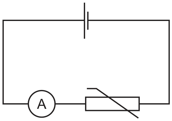
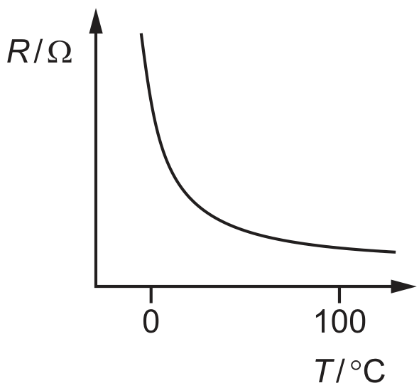
Which diagram could represent the temperature scale on the ammeter?
The diagram shows a calibration curve for a thermistor, drawn with an unusual scale on the vertical axis.
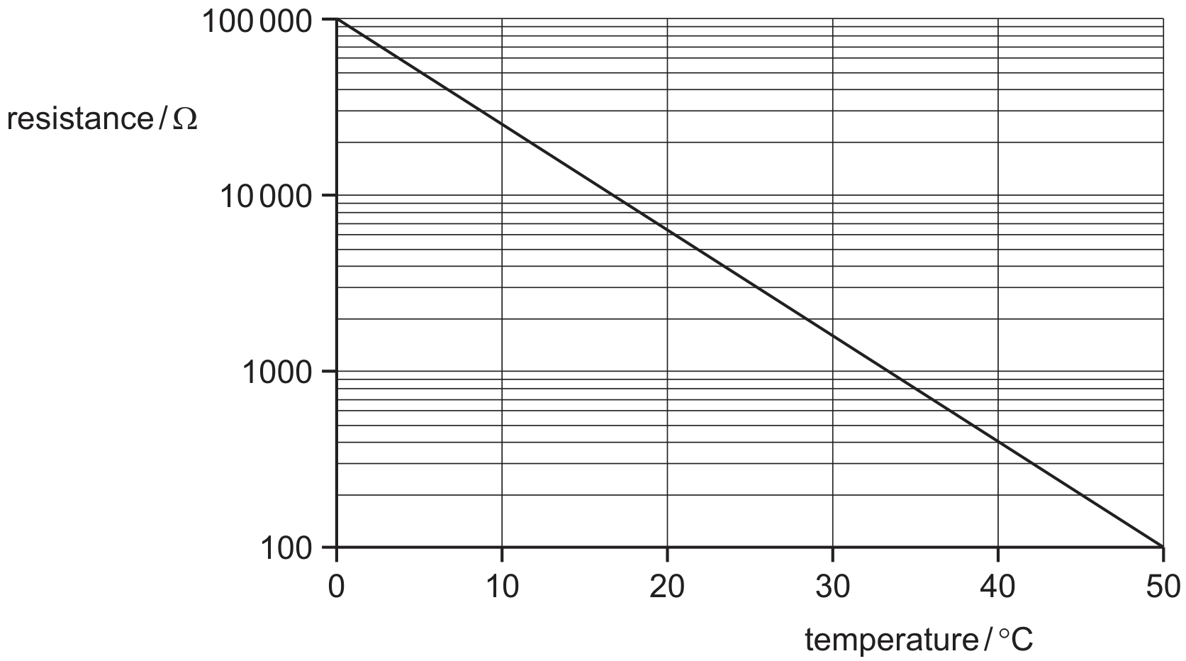
What is the thermistor resistance corresponding to a temperature of ?
Define electrical resistance.
(b) A circuit is set up to measure the resistance R of a metal wire. The potential difference (p.d.) V across the wire and the current I in the wire are to be measured.
(i) Draw a circuit diagram of the apparatus that could be used to make these measurements.
(b) A circuit is set up to measure the resistance R of a metal wire. The potential difference (i)
Use data from Fig. 2.1 to determine R. Explain your working.
The resistance R of a uniform metal wire is measured for different lengths l of the wire. The variation with l of R is shown in Fig. 3.1.
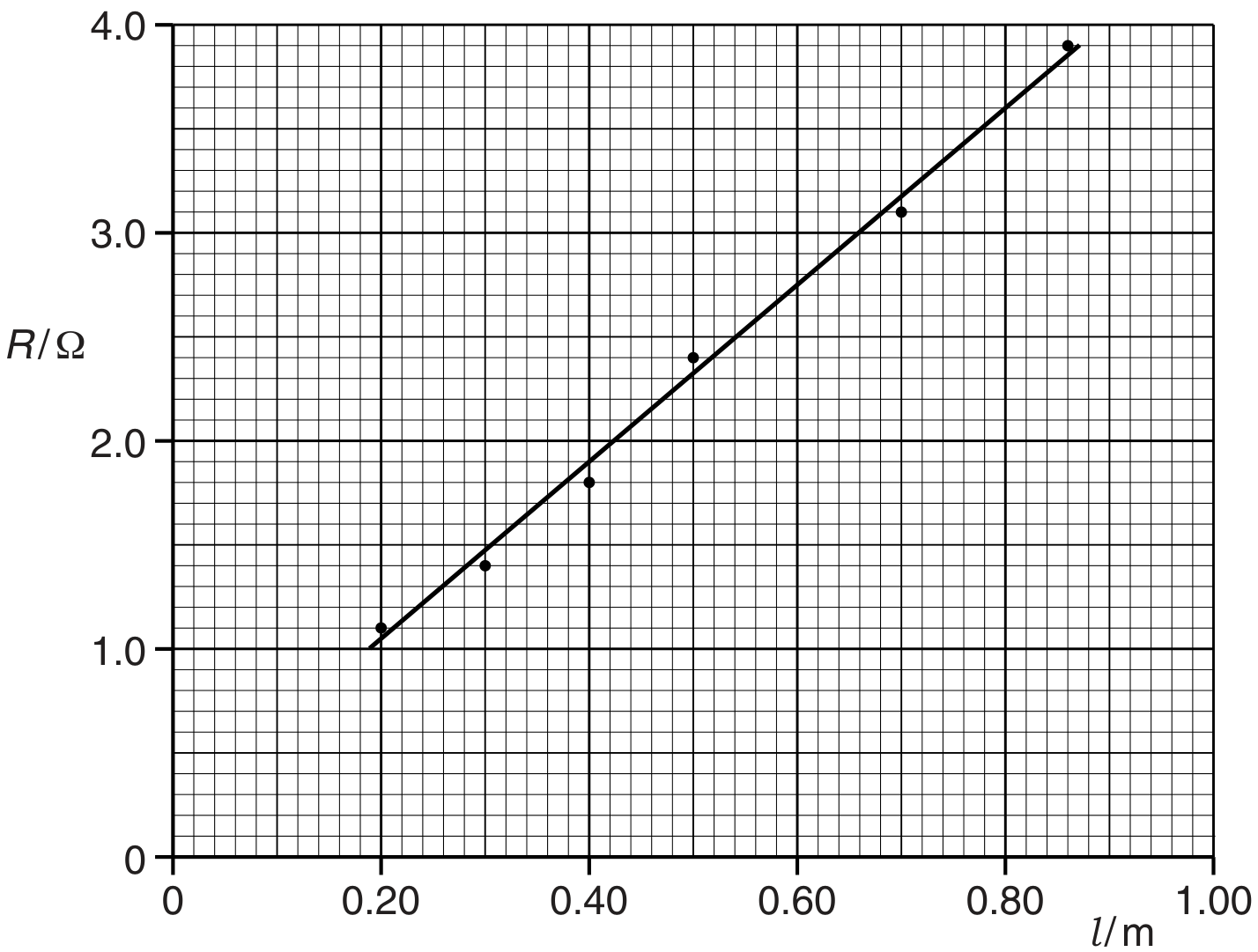
Fig. 3.1
The cross-sectional area of the wire is .
Use your answer in (b) to determine the resistivity of the metal of the wire.
The resistance R of different wires is measured. The wires are of the same metal and same length but have different cross-sectional areas A.
On Fig. 3.2, sketch a graph to show the variation with A of R.
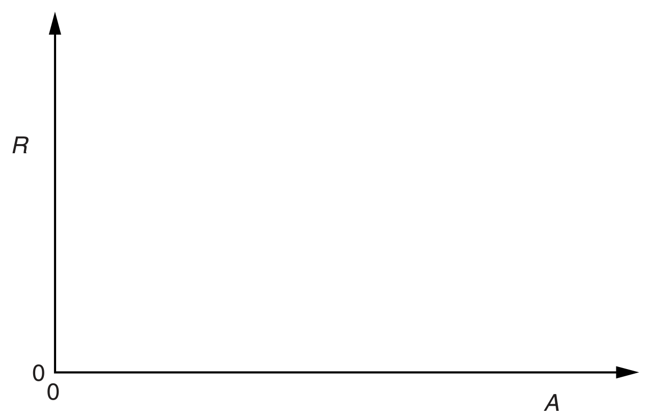
Fig. 3.2
Lightning occurs when charge builds up in the atmosphere, creating a potential difference between the ground and the atmosphere.
During a lightning strike there is an average current of for a time of .
A lightning rod is attached to a tall building to conduct charge safely to the ground. The lightning rod is modelled as a uniform cylindrical copper cable of total length 95 m that runs from the ground to the top of the building, as shown in Fig. 3.1.
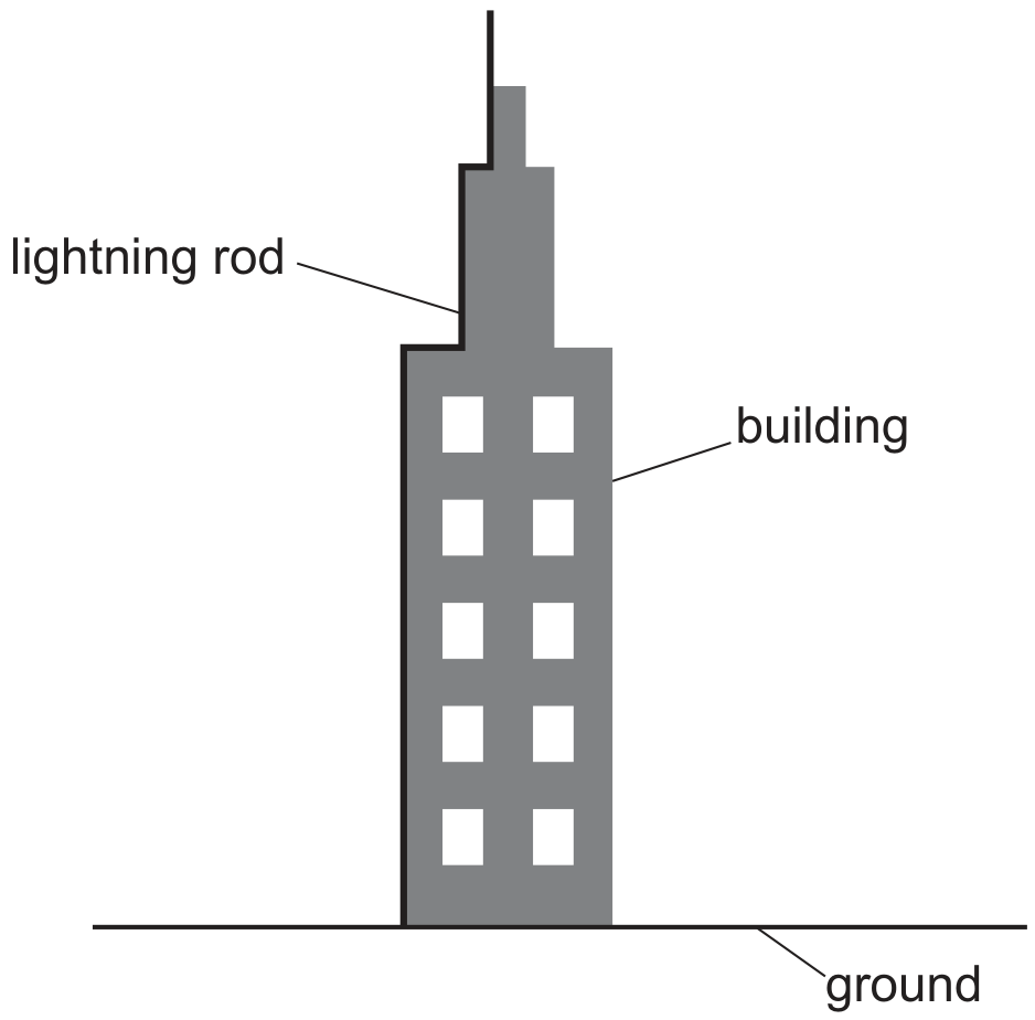
Fig. 3.1


The resistance of the lightning rod is .
The resistivity of copper is .
Determine the radius of the lightning rod.
radius = m
The radius of the copper lightning rod is doubled with no change to its length.
State the effect of this change on the resistance of the lightning rod.
The variation with potential difference (p.d.) V of current I for a semiconductor diode is shown in Fig. 5.1.
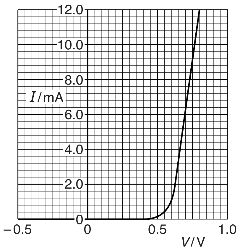
Fig. 5.1
Use Fig. 5.1 to describe the variation of the resistance of the diode between and .
On Fig. 5.2, sketch the variation with p.d. V of current I for a filament lamp. Numerical values are not required.
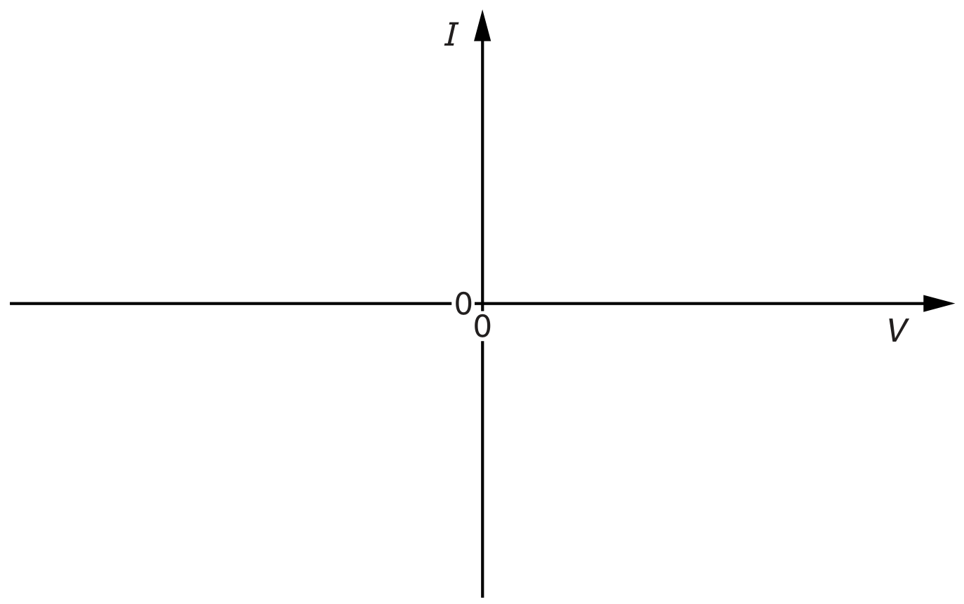
Fig. 5.2
Fig. 5.3 shows a power supply of electromotive force (e.m.f.) 12 V and internal resistance connected to a filament lamp and switch.
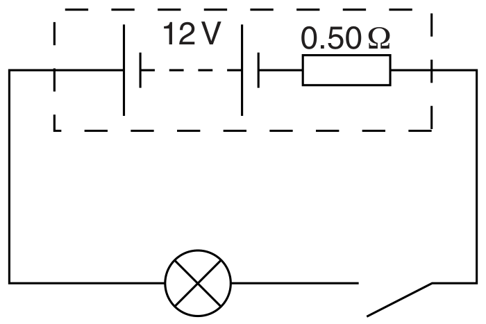
Fig. 5.3
The filament lamp has a power of 36 W when the p.d. across it is 12 V .
Calculate the resistance of the lamp when the p.d. across it is 12 V .
resistance =
The switch is closed and the current in the lamp is 2.8 A . Calculate the resistance of the lamp.
resistance =
Explain how the two values of resistance calculated in (c) provide evidence for the shape of the sketch you have drawn in (b).
A uniform wire has length L and constant area of cross-section A. The material of the wire has Young modulus E and resistivity . A tension F in the wire causes its length to increase by .
For this wire, state expressions, in terms of and for
the resistance R.
One end of a metal wire of length 2.6 m and constant area of cross-section is attached to a fixed point, as shown in Fig. 4.1.
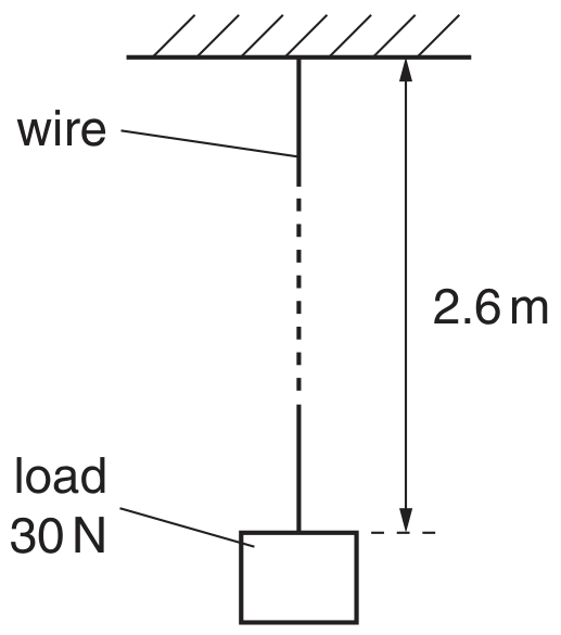
Fig. 4.1
The Young modulus of the material of the wire is and its resistivity is .
A load of 30 N is attached to the lower end of the wire. Assume that the area of cross-section of the wire does not change.
For this load of 30 N ,
calculate the change in resistance of the wire.
change =
The resistance of the wire changes with the applied load.
Comment on the suggestion that this change of resistance could be used to measure the magnitude of the load on the wire.
A sinusoidal alternating voltage supply is connected to a bridge rectifier consisting of four ideal diodes. The output of the rectifier is connected to a resistor R and a capacitor C as shown in Fig. 6.1.
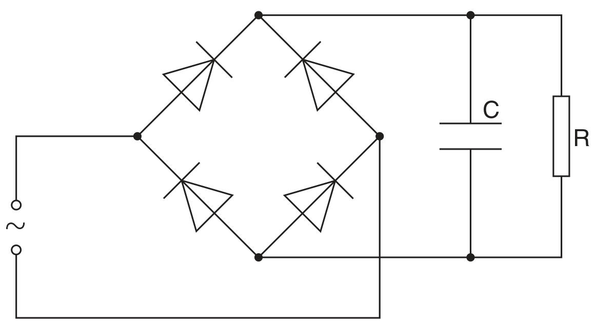
Fig. 6.1
The function of C is to provide some smoothing to the potential difference across R .
The variation with time t of the potential difference V across the resistor R is shown in Fig. 6.2.
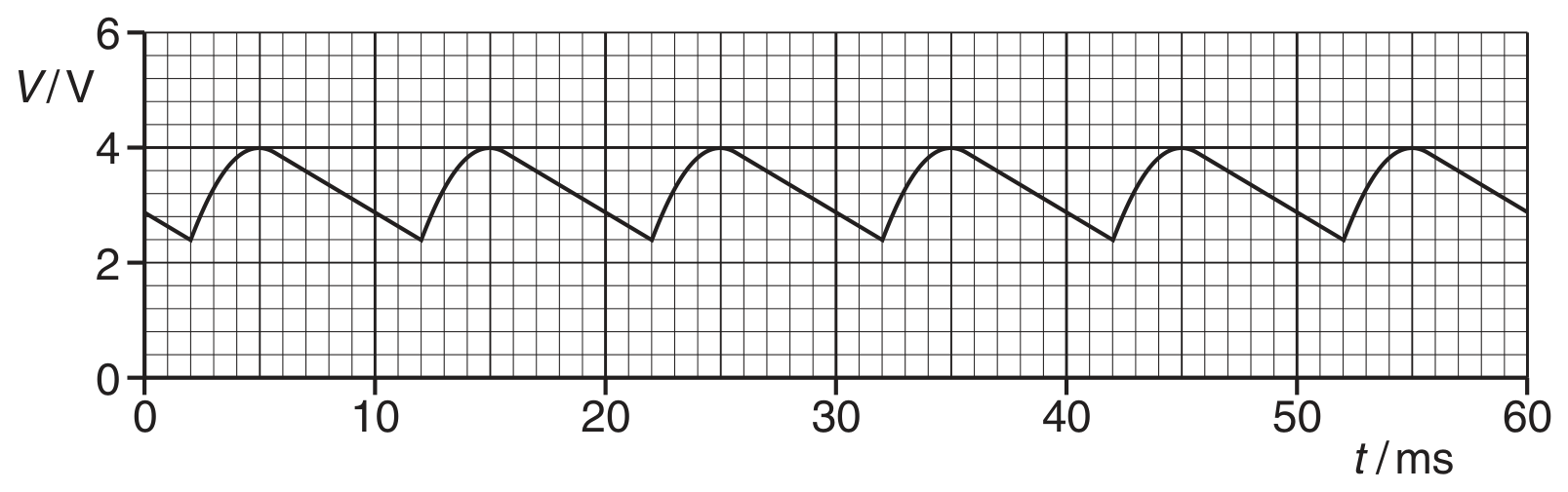
Fig. 6.2
Use Fig. 6.2 and the value of the current given in (b)(iii) to estimate the resistance of resistor R .
resistance =
On Fig. 5.1, sketch the temperature characteristic of a thermistor.
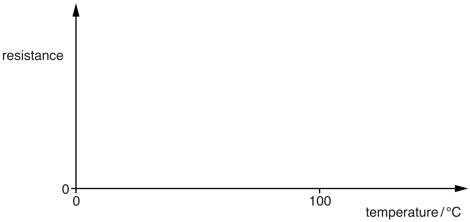
Fig. 5.1
A potential divider circuit is shown in Fig. 5.2.
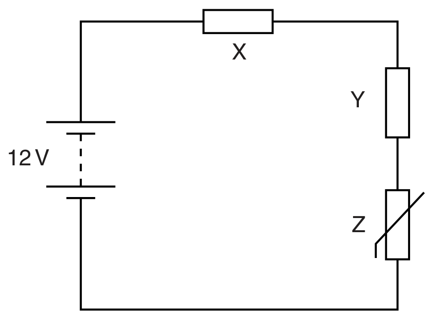
Fig. 5.2
The battery of electromotive force (e.m.f.) 12 V and negligible internal resistance is connected in series with resistors X and Y and thermistor Z. The resistance of Y is and the resistance of Z at a particular temperature is . The potential difference (p.d.) across Y is 8.0 V .
Calculate the resistance of X.
resistance = ..... .....
The temperature of Z is increased.
State and explain the effect on the potential difference across Z.