EduNinja
[Maximum number: 1]

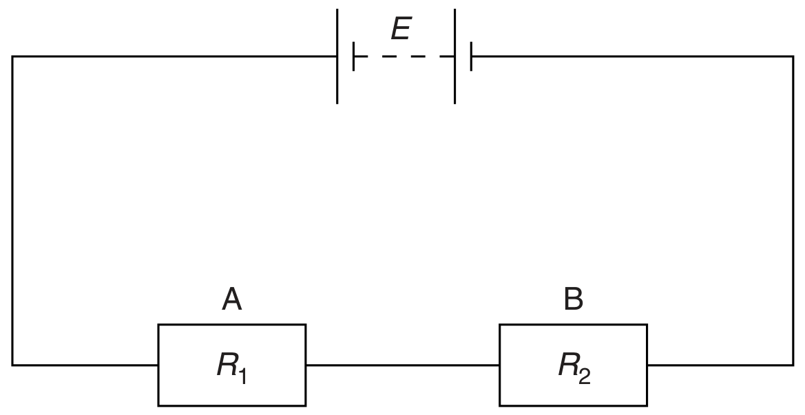
A power supply of electromotive force (e.m.f.) 50 V and negligible internal resistance is connected in series with resistors of resistance 100Ω100 \Omega and 5Ω5 \Omega, as shown.

Question image

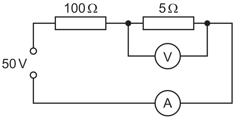
A voltmeter measures the potential difference (p.d.) across the 5Ω5 \Omega resistor and an ammeter measures the current in the circuit.

What are suitable ranges for the ammeter and for the voltmeter?

ammeter

range / A

voltmeter

range /V

0-0.1

0-1

0-0.1

0-3

0-1.0

0-1

0-1.0

0-3

(a)
(i)

Draw a circuit diagram of the apparatus that could be used to make these
measurements.

[ 3 ]
(a)

Explain why the terminal potential difference (p.d.) of a cell with internal resistance may be less than the electromotive force (e.m.f.) of the cell.

[ 2 ]
(b)

A battery of e.m.f. 4.5 V and internal resistance r is connected in series with a resistor of resistance 6.0Ω6.0 \Omega, as shown in Fig. 5.1.

Fig. 5.1

Fig. 5.1

The current I in the circuit is 0.65 A .
Determine

[ 2 ]
(i)

the internal resistance r of the battery,

(ii)

the terminal p.d. of the battery,
p.d. = V

[ 2 ]
(c)

A second resistor of resistance 20Ω20 \Omega is connected in parallel with the 6.0Ω6.0 \Omega resistor in Fig. 5.1. Describe and explain qualitatively the change in the heating effect within the battery.

[ 3 ]
[Maximum number: 3]

A circuit used to measure the power transfer from a battery is shown in Fig. 4.1. The power is transferred to a variable resistor of resistance R.

Fig. 4.1

Fig. 4.1

The battery has an electromotive force (e.m.f.) E and an internal resistance r. There is a potential difference (p.d.) V across R. The current in the circuit is I.

(a)

By reference to the circuit shown in Fig. 4.1, distinguish between the definitions of e.m.f. and p.d.

[ 3 ]
(b)

The variation with current I of the p.d. V across R is shown in Fig. 4.2.

Fig. 4.2

Fig. 4.2

Use Fig. 4.2 to determine

(i)

the e.m.f. E,

(ii)

the internal resistance r.

(a)

Distinguish between potential difference (p.d.) and electromotive force (e.m.f.) in terms of energy transformations.

[ 2 ]
(b)

Two cells A and B are connected in series with a resistor R of resistance 5.5Ω5.5 \Omega, as shown in Fig. 4.1.

Fig. 4.1

Fig. 4.1

Cell A has e.m.f. 4.4 V and internal resistance 2.3Ω2.3 \Omega. Cell B has e.m.f. 2.1 V and internal resistance 1.8Ω1.8 \Omega.

[ 3 ]
(i)

On Fig. 4.1, draw an arrow to show the direction of the current in the circuit. Label this arrow I.

[ 1 ]
(ii)

Calculate
1. the p.d. across resistor R,
2. the terminal p.d. across cell A,
3. the terminal p.d. across cell B.

p.d. =V [2]
[ 2 ]
(a)

A potential divider circuit is shown in Fig. 5.2.

Fig. 5.2

Fig. 5.2

The battery of electromotive force (e.m.f.) 12 V and negligible internal resistance is connected in series with resistors X and Y and thermistor Z. The resistance of Y is 15kΩ15 \mathrm{k} \Omega and the resistance of Z at a particular temperature is 3.0kΩ3.0 \mathrm{k} \Omega. The potential difference (p.d.) across Y is 8.0 V .

[ 1 ]
(i)

Explain why the power transformed in the battery equals the total power transformed in X, Y and Z.

[ 1 ]
[Maximum number: 3]

A battery is connected in series with resistors X and Y, as shown in Fig. 6.1.

Fig. 6.1

Fig. 6.1

The resistance of X is constant. The resistance of Y is 6.0Ω6.0 \Omega. The battery has electromotive force (e.m.f.) 24 V and zero internal resistance. A variable resistor of resistance R is connected in parallel with X.

The current I from the battery is changed by varying R from 5.0Ω5.0 \Omega to 20Ω20 \Omega. The variation with R of I is shown in Fig. 6.2.

Fig. 6.2

Fig. 6.2

(a)

Explain why the potential difference (p.d.) between points A and C is 24 V for all values of R.

[ 1 ]
(b)

Use Fig. 6.2 to state and explain the variation of the p.d. across resistor Y as R is increased. Numerical values are not required.

[ 2 ]
[Maximum number: 3]

Two resistors A and B have resistances R1R_{1} and R2R_{2} respectively. The resistors are connected in series with a battery, as shown in Fig. 6.1.

Fig. 6.1

Fig. 6.1

The battery has electromotive force (e.m.f.) E and zero internal resistance.

(a)

State the energy transformation that occurs in

[ 2 ]
(i)

the battery,

[ 1 ]
(ii)

the resistors.

[ 1 ]
(b)

The current in the circuit is I.

State the rate of energy transformation in

[ 1 ]
(i)

the battery,

[ 1 ]
[Maximum number: 3]

A student sets up a circuit with a battery, an ammeter, a heater and a light-dependent resistor (LDR) all in series.

The battery has negligible internal resistance.
A voltmeter is connected across (in parallel with) the heater.

(a)

On Fig. 5.1, complete the circuit diagram of this arrangement.

Fig. 5.1

Fig. 5.1

[ 3 ]
(a)

The electromotive force (e.m.f.) of the cell in Fig. 6.1 is 1.50 V .

The values of R1R_{1} and R2R_{2} are 10Ω10 \Omega and 15Ω15 \Omega respectively. The terminal p.d. of the cell is 1.35 V .
Calculate the internal resistance r of the cell.

r=
[ 2 ]
(b)

A resistor of resistance R3R_{3} is added to the circuit in Fig. 6.1, so that the circuit is as shown in Fig. 6.2.

Fig. 6.2

Fig. 6.2

State and explain the effect, if any, of this change on:

[ 4 ]
(i)

the current in the cell

[ 2 ]
(ii)

the terminal p.d. of the cell.

[ 2 ]
0