[Maximum number: 2]
Energy is stored in a metal wire that is extended elastically.
(a)
Explain what is meant by extended elastically.
[ 2 ]
 EduNinja
Energy is stored in a metal wire that is extended elastically.
Explain what is meant by extended elastically.
A sphere is attached by a metal wire to the horizontal surface at the bottom of a river, as shown in Fig. 2.1.
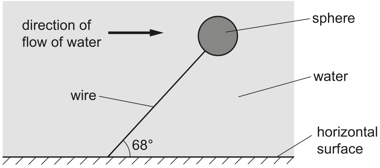
Fig. 2.1 (not to scale)
The sphere is fully submerged and in equilibrium, with the wire at an angle of to the horizontal surface. The weight of the sphere is 32 N . The upthrust acting on the sphere is 280 N . The density of the water is .
Assume that the force on the sphere due to the water flow is in a horizontal direction.
The extension of the wire increases when the sphere changes position as described in (c). The wire obeys Hooke's law.
Before the sphere changed position, the initial elastic potential energy of the wire was 0.65 J . The change in position of the sphere causes the extension of the wire to double.
Calculate the final elastic potential energy of the wire after the sphere has changed position.
A hot-air balloon floats just above the ground. The balloon is stationary and is held in place by a vertical rope, as shown in Fig. 2.1.
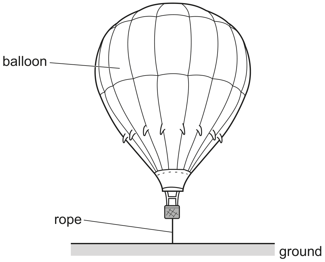
Fig. 2.1
The balloon has a weight W of . The tension T in the rope is .
Upthrust U acts on the balloon.
The density of the surrounding air is .
Before the balloon is released, the rope holding the balloon has a strain of . The rope has an unstretched length of 2.5 m . The rope obeys Hooke's law.
Calculate the elastic potential energy of the rope.
A thin metal wire X , of diameter , is used to suspend a model planet, as shown in Fig. 3.1.
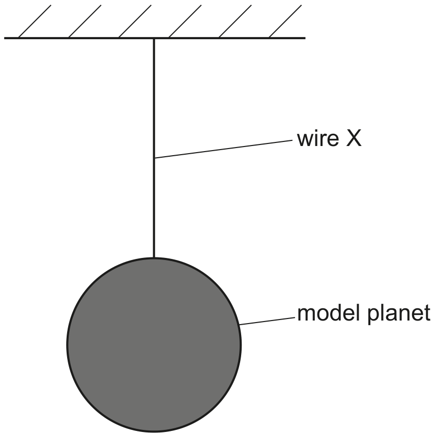
Fig. 3.1 (not to scale)
The variation with strain of the stress for wire X is shown in Fig. 3.2.
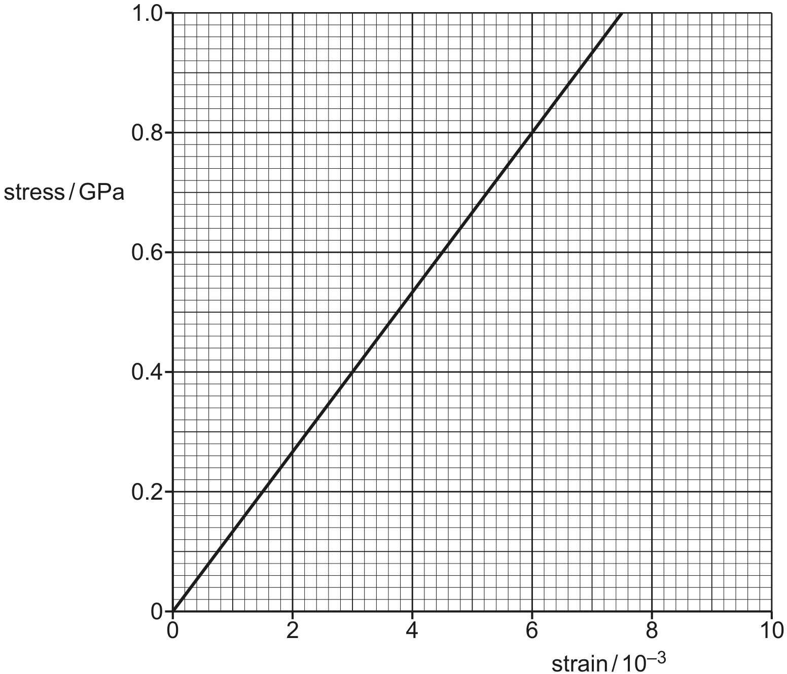
Fig. 3.2
The strain in X is .
The elastic potential energy of X is 0.31 J .
Calculate the original length of the wire before the model planet was attached.
original length = m
The system shown in Fig. 3.1 is part of a mechanism that controls the amount of water in a tank.
Water enters the tank and causes the sphere to rise. This results in the bar becoming horizontal. Fig. 3.2 shows the system in its new position.
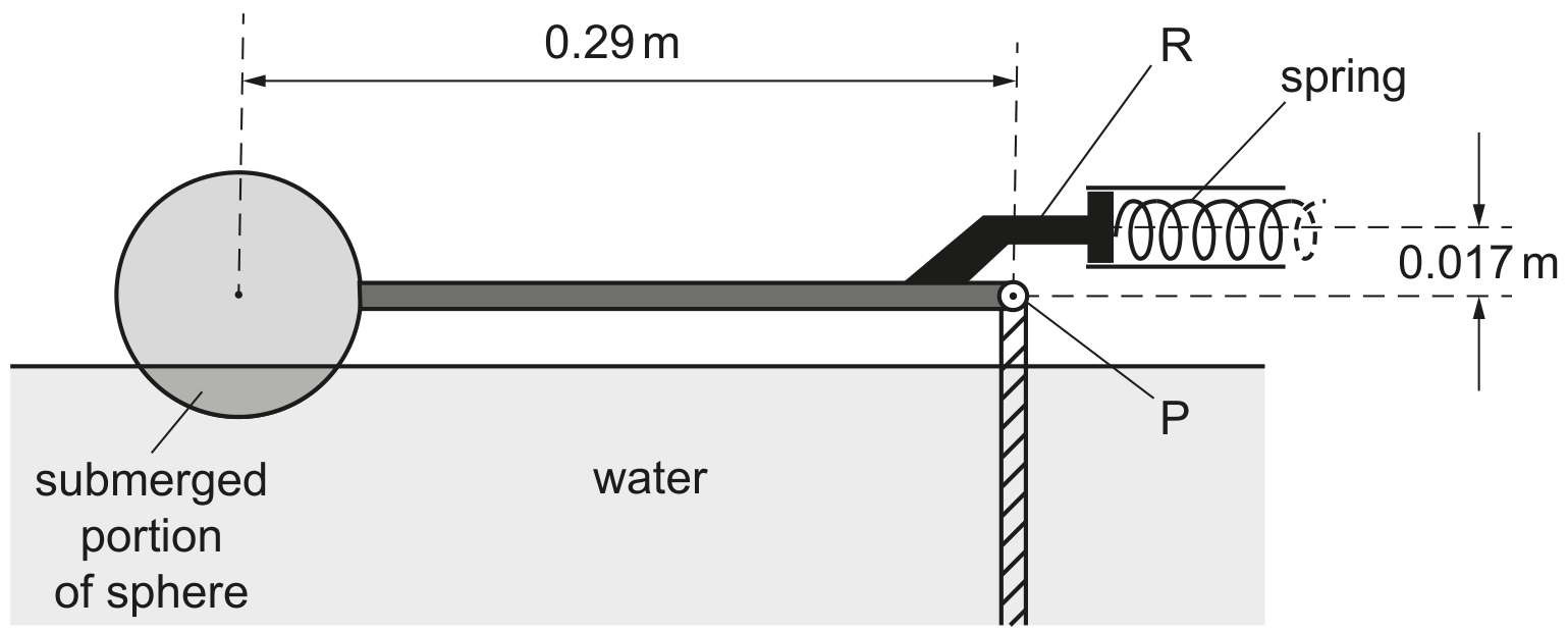
Fig. 3.2 (not to scale)
In this position the rod R exerts a force to compress a horizontal spring that controls the water supply to the tank. R is positioned at a perpendicular distance of 0.017 m above P.
The variation of the force F applied to the spring with compression x of the spring is shown in Fig. 3.3.
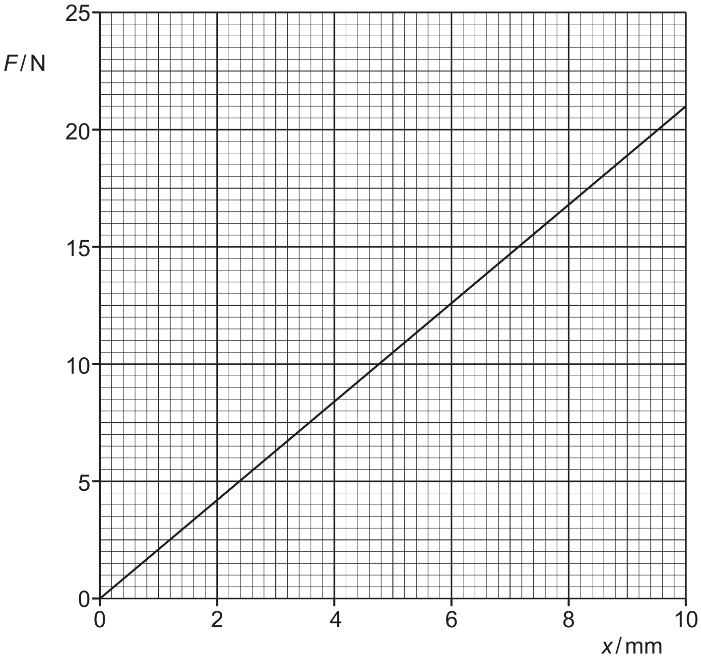
Fig. 3.3
Calculate the elastic potential energy of the compressed spring.
When the sphere moves from the position shown in Fig. 3.1 to the position shown in Fig. 3.2, the upthrust on the sphere does work.
Assume that resistive forces are negligible.
Explain why the work done by the upthrust is not equal to the gain in elastic potential energy of the spring.
One end of a spring is fixed to a support. A mass is attached to the other end of the spring. The arrangement is shown in Fig. 3.1.
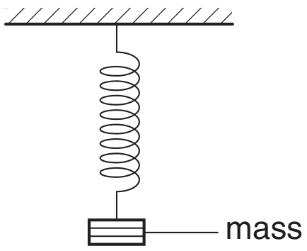
Fig. 3.1
The mass is pulled down and then released at time t=0. The mass oscillates up and down. The variation with t of the displacement of the mass d is shown in Fig. 3.2.
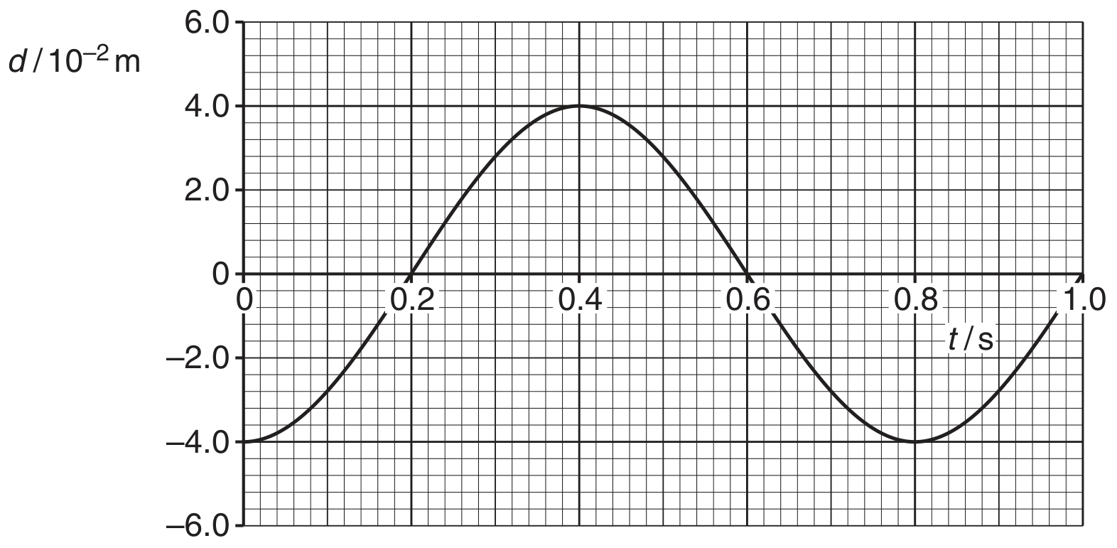
Fig. 3.2
Use Fig. 3.2 to state a time, one in each case, when
the mass is at maximum speed,
the elastic potential energy stored in the spring is a maximum,
The arrangement shown in Fig. 3.3 is used to determine the length l of a spring when different masses M are attached to the spring.
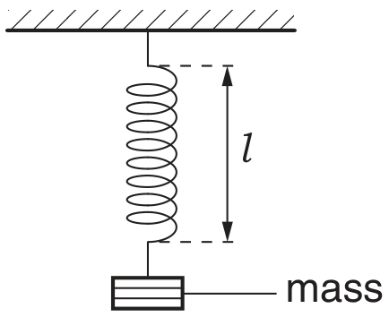
Fig. 3.3
The variation with mass M of l is shown in Fig. 3.4.
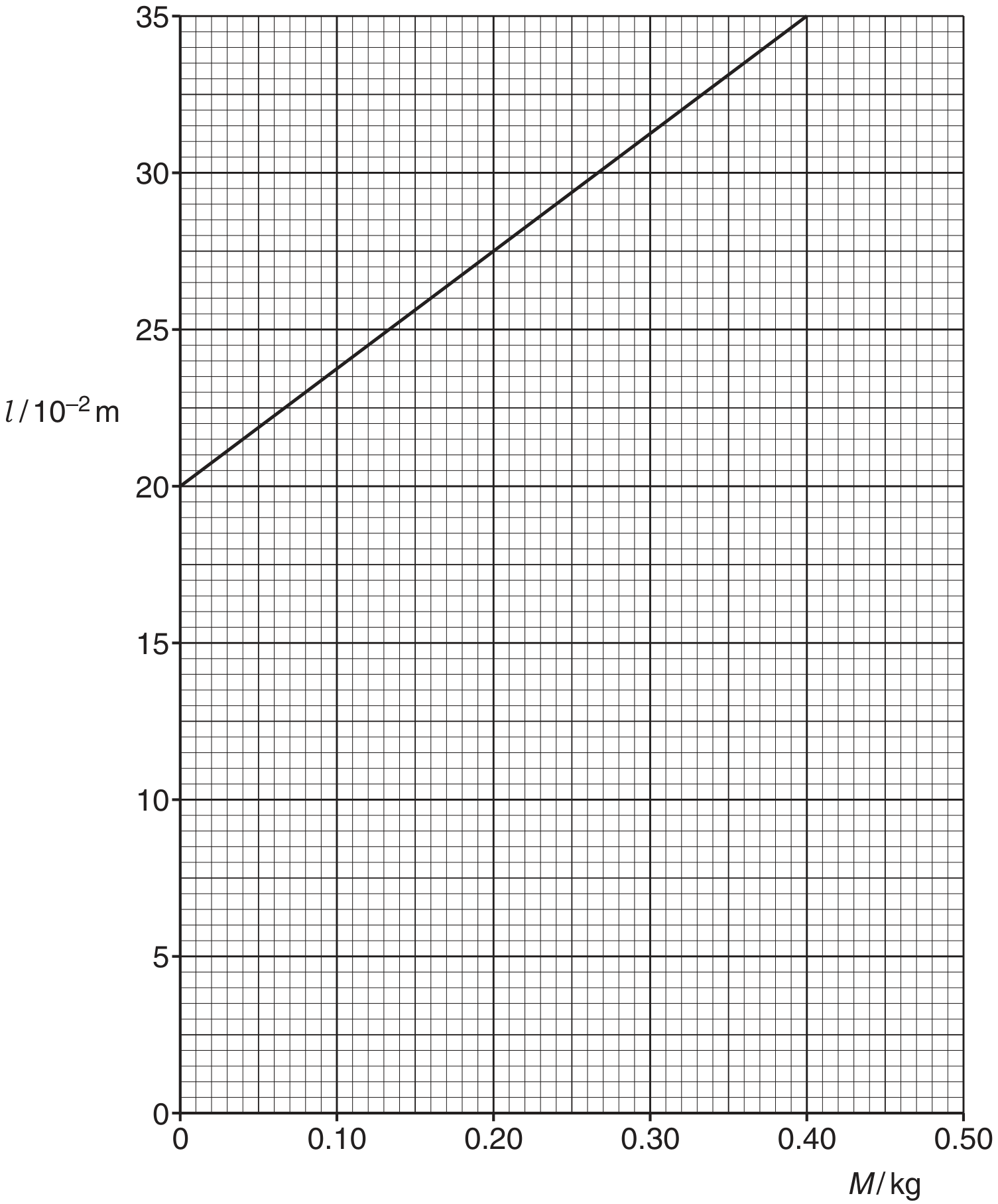
Fig. 3.4
A mass of 0.40 kg is attached to the spring. Calculate the energy stored in the spring.
energy = J
Explain the term elastic limit.
Explain the term ultimate tensile stress.
A ductile material in the form of a wire is stretched up to its breaking point. On Fig. 3.1, sketch the variation with extension x of the stretching force F.
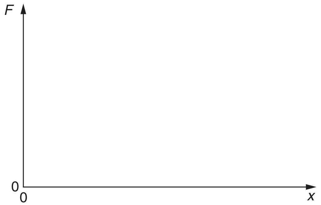
Fig. 3.1
On Fig. 3.2, sketch the variation with x of F for a brittle material up to its breaking point.
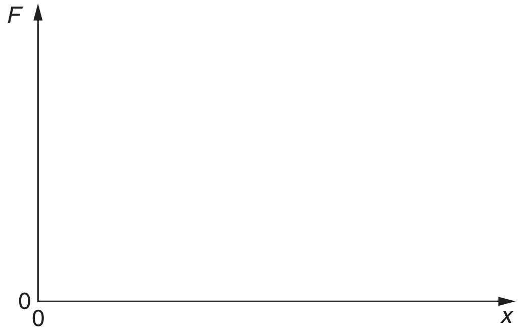
Fig. 3.2
Explain the features of the graphs in (d) that show the characteristics of ductile and brittle materials.
The force F is removed from the materials in (d) just before the breaking point is reached. Describe the subsequent change in the extension for
1. the ductile material,
2. the brittle material.
A small electric motor is mounted on a bench, as shown. The motor is connected to a 6.0 V supply and the current in the motor is 0.50 A . The motor is 50 % efficient.
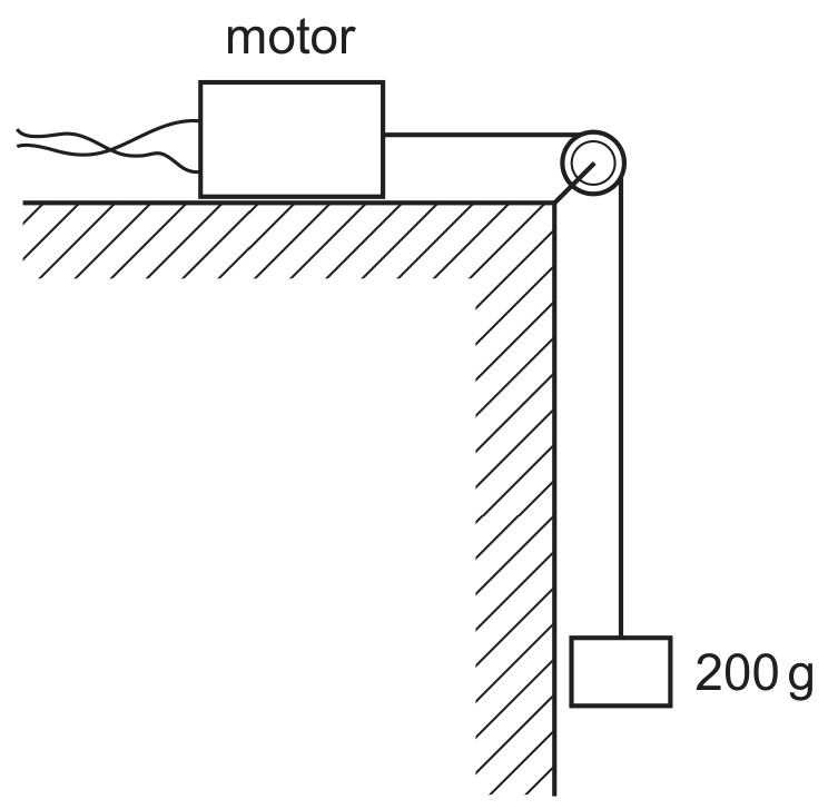
What is the time taken to lift a mass of 200 g up through a height of 90 cm ?
0.85 s
1.2 s
A spring is kept horizontal by attaching it to points A and B , as shown in Fig. 4.1.
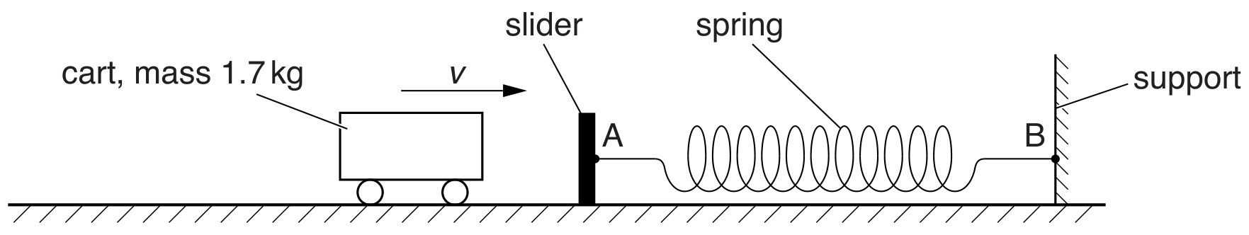
Fig. 4.1
Point A is on a movable slider and point B is on a fixed support. A cart of mass 1.7 kg has horizontal velocity v towards the slider. The cart collides with the slider. The spring is compressed as the cart comes to rest. The variation of compression x of the spring with force F exerted on the spring is shown in Fig. 4.2.
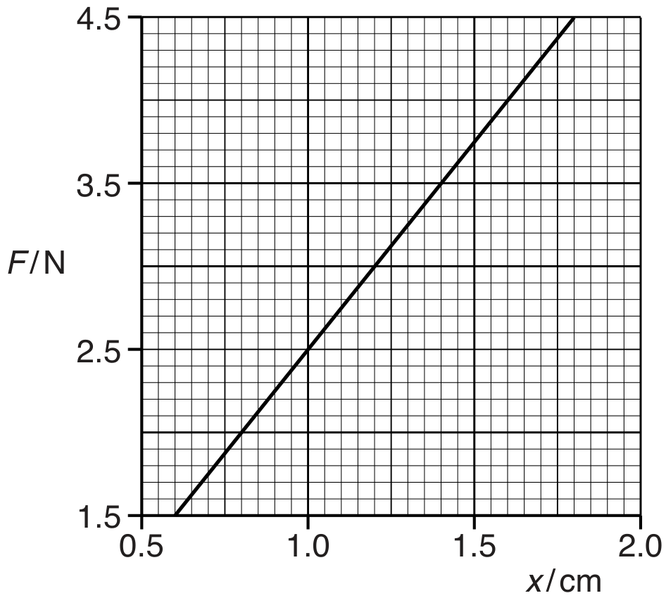
Fig. 4.2
Fig. 4.2 shows the compression of the spring for to . The cart comes to rest when F is 4.5 N .
Use Fig. 4.2 to
determine the elastic potential energy stored in the spring due to the cart being brought to rest.
J
The variation of the applied force with the extension for a sample of a material is shown in Fig. 3.1.
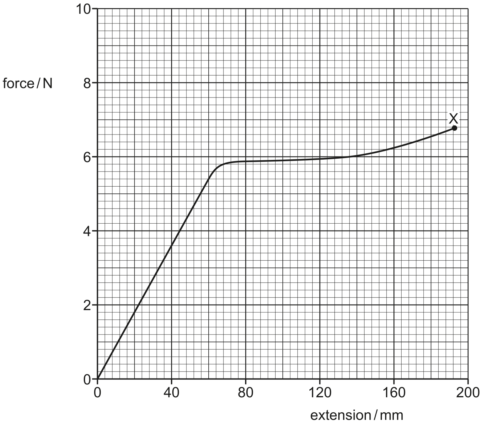
Fig. 3.1
The sample behaves elastically up to an extension of 80 mm and breaks at point X .
On the line in Fig. 3.1, draw a cross ( x ) to show the limit of proportionality. Label this cross with the letter P .
On the line in Fig. 3.1, draw a cross ( ) to show the elastic limit. Label this cross with the letter E.
Determine an estimate of the work done on the sample as it is extended from zero extension to its breaking point. Explain your reasoning.
work done = J