(a)
Define potential difference.
[ 1 ]
 EduNinja
Define potential difference.
Which physical quantity would result from a calculation in which a potential difference is multiplied by an electric charge?
electric current
electric energy
electric field strength
electric power
What is a possible unit for the product V I, where V is the potential difference across a resistor and I is the current through the same resistor?
newton per second ( )
newton second (Ns)
newton metre ( Nm )
newton metre per second ( )
Which physical quantity would result from a calculation in which a potential difference is multiplied by an electric charge?
electric current
electric energy
electric field strength
electric power
Lightning occurs when charge builds up in the atmosphere, creating a potential difference between the ground and the atmosphere.
During a lightning strike there is an average current of for a time of .
The potential difference between the ground and the atmosphere is .
Calculate the average power, in GW, transferred during the lightning strike.
power = GW
An uncharged capacitor is connected in series with a battery, a switch and a resistor, as shown in Fig. 6.1.
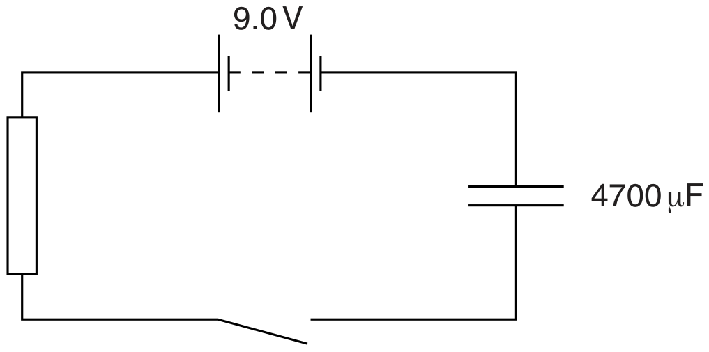
Fig. 6.1
The battery has e.m.f. 9.0 V and negligible internal resistance. The capacitance of the capacitor is .
The switch is closed at time t=0.
During the time interval t=0 to , the charge passing through the resistor is 22 mC .
Calculate the energy transfer in the battery during the time interval t=0 to .
energy transfer = J
A circuit used to measure the power transfer from a battery is shown in Fig. 4.1. The power is transferred to a variable resistor of resistance R.
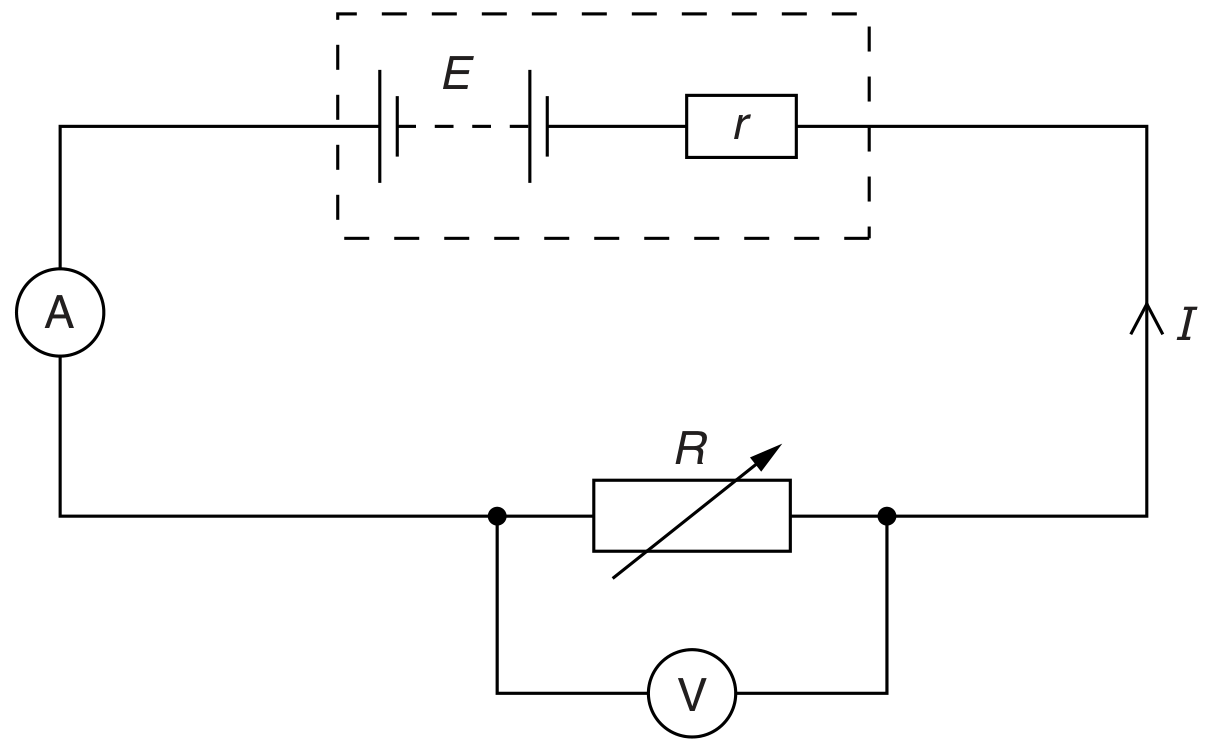
Fig. 4.1
The battery has an electromotive force (e.m.f.) E and an internal resistance r. There is a potential difference (p.d.) V across R. The current in the circuit is I.
Using data from Fig. 4.2, calculate the power transferred to R for a current of 1.6 A .
power = W
The supply voltage is changed to 110 V .
Calculate the power output of the heater at this voltage, assuming there is no change in the resistance of the wire.
power = W
Two resistors A and B have resistances and respectively. The resistors are connected in series with a battery, as shown in Fig. 6.1.
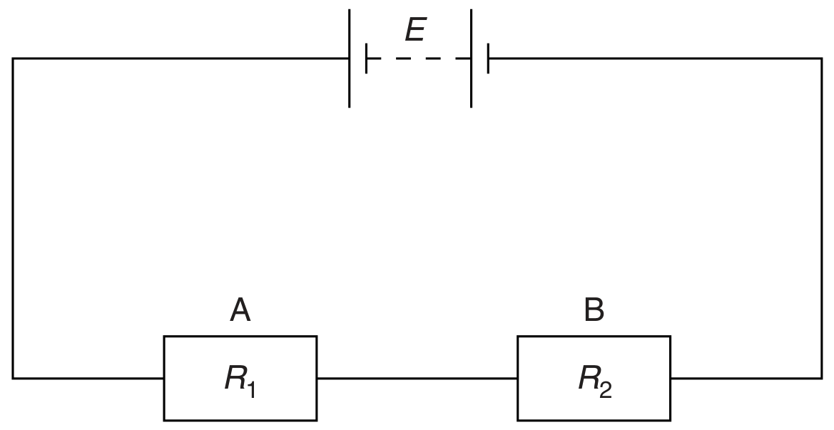
Fig. 6.1
The battery has electromotive force (e.m.f.) E and zero internal resistance.
The current in the circuit is I.
State the rate of energy transformation in
the resistor A .
The resistors are made from metal wires. Data for the resistors are given in Fig. 6.2.
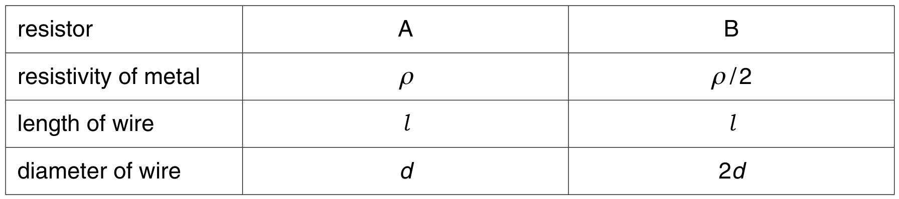
Fig. 6.2
Use information from Fig. 6.2 to determine the ratio
power dissipated in A
power dissipated in B .
ratio =
The resistors A and B are connected in parallel across the same battery of e.m.f. E. Determine the ratio
power dissipated in A
power dissipated in B .
ratio =
An electric heater is to be made from nichrome wire. Nichrome has a resistivity of at the operating temperature of the heater.
The heater is to have a power dissipation of 60 W when the potential difference across its terminals is 12 V .
A second heater, also designed to operate from a 12 V supply, is constructed using the same nichrome wire but using half the length of that calculated in (b). Explain quantitatively the effect of this change in length of wire on the power of the heater.