IB Physics SL B.5 Current & circuits Question Bank

Practise extracting circuit quantities from diagrams and graphs, applying charge, resistance and power relations and checking cell or meter assumptions.

Syllabus
First assessment 2025
Topic
Level
SL

Exam points

  • define emf as energy per charge and calculate current from charge flow or conventional-current direction
  • calculate resistance or resistivity and distinguish ohmic from non-ohmic V-I behaviour
  • reduce series-parallel networks and apply Kirchhoff junction or loop rules with ideal meters
  • calculate terminal potential difference using emf and internal resistance as load changes
  • calculate electrical power, energy or rms current and compare useful transfer or dissipation

B.5 Current and circuits question 1

[Maximum number: 8]

This question is in two parts. Part 1 is about a thermistor circuit. Part 2 is about vibrations and waves.
Part 1 Thermistor circuit
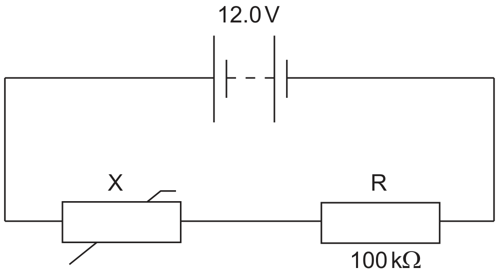
The circuit shows a negative temperature coefficient (NTC) thermistor X and a 100kΩ100 \mathrm{k} \Omega fixed resistor R connected across a battery.

Figure for Question B.5 Current and circuits question 1 — IB Physics SL

The battery has an electromotive force (emf) of 12.0 V and negligible internal resistance.

Question (a)

(a)

Define electromotive force (emf).

[ 1 ]

Question (b)

(b)

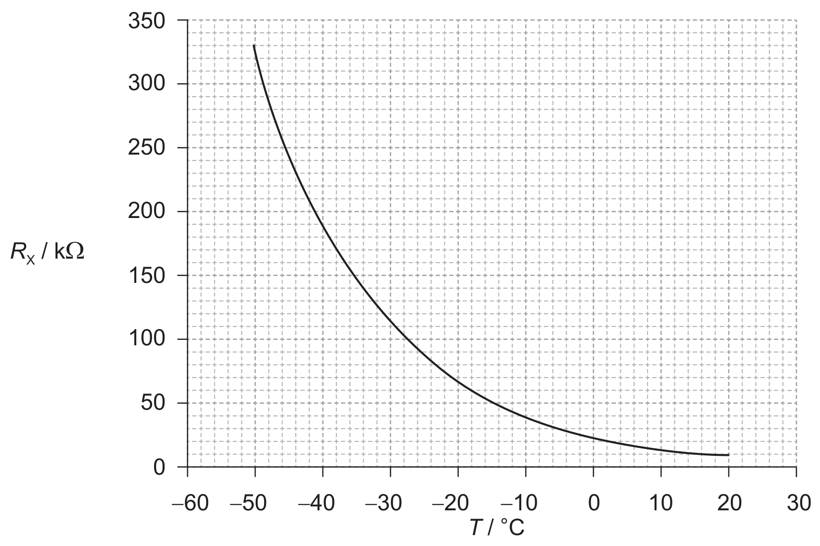
The graph below shows the variation with temperature T of the resistance RxR_{\mathrm{x}} of the thermistor.

Figure for Question (b) — IB Physics SL
[ 7 ]

Question (i)

(i)

Determine the temperature of X when the potential difference across R is 4.5 V .

[ 4 ]

Question (ii)

(ii)

State the range of temperatures for which the change in the resistance of the thermistor is most sensitive to changes in temperature.

[ 1 ]

Question (iii)

(iii)

State and explain the effect of a decrease in temperature on the ratio

 voltage across X voltage across R\frac{\text { voltage across } \mathrm{X}}{\text { voltage across } \mathrm{R}}

Part 2 Vibrations and waves

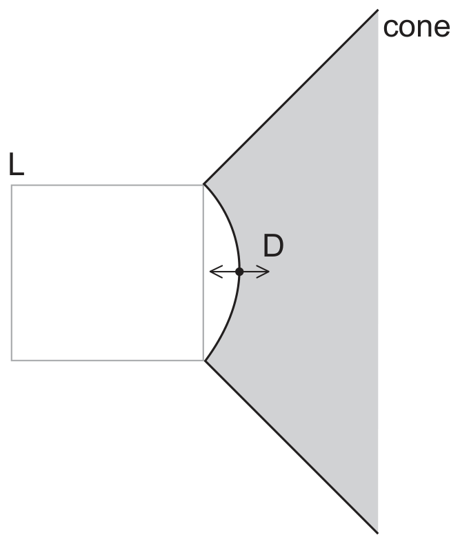
The cone and dust cap D of a loudspeaker L vibrates with a frequency of 1.25 kHz with simple harmonic motion (SHM).

Figure for Question (iii) — IB Physics SL
[ 2 ]

B.5 Current and circuits question 2

[Maximum number: 9]

Question (a)

(a)

Identify the laws of conservation that are represented by Kirchhoff's circuit laws.

[ 2 ]

Question (b)

(b)

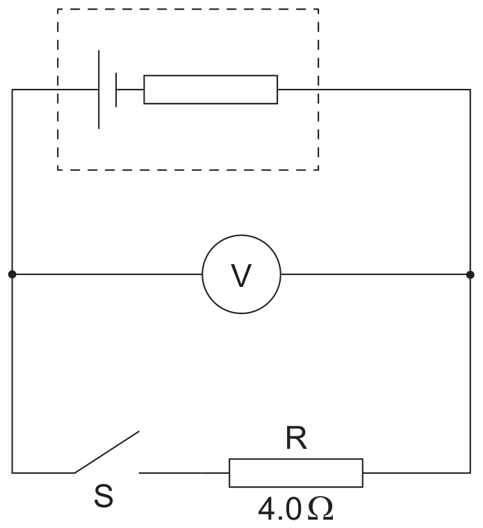
A cell is connected to an ideal voltmeter, a switch S and a resistor R. The resistance of R is 4.0Ω4.0 \Omega.

Figure for Question (b) — IB Physics SL

When S is open the reading on the voltmeter is 12 V . When S is closed the voltmeter reads 8.0 V .

[ 3 ]

Question (i)

(i)

State the emf of the cell.

[ 1 ]

Question (ii)

(ii)

Deduce the internal resistance of the cell.

[ 2 ]

Question (c)

(c)

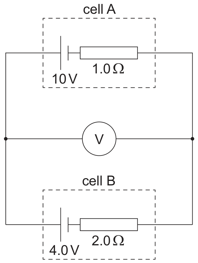
The voltmeter is used in another circuit that contains two secondary cells.

Figure for Question (c) — IB Physics SL

Cell A has an emf of 10 V and an internal resistance of 1.0Ω1.0 \Omega. Cell B has an emf of 4.0 V and an internal resistance of 2.0Ω2.0 \Omega.

Calculate the reading on the voltmeter.

[ 3 ]

Question (d)

(d)

Outline why research into solar cell technology is important to society.

[ 1 ]

B.5 Current and circuits question 3

[Maximum number: 10]

Question (a)

(a)

Part 2 Electric current and resistance
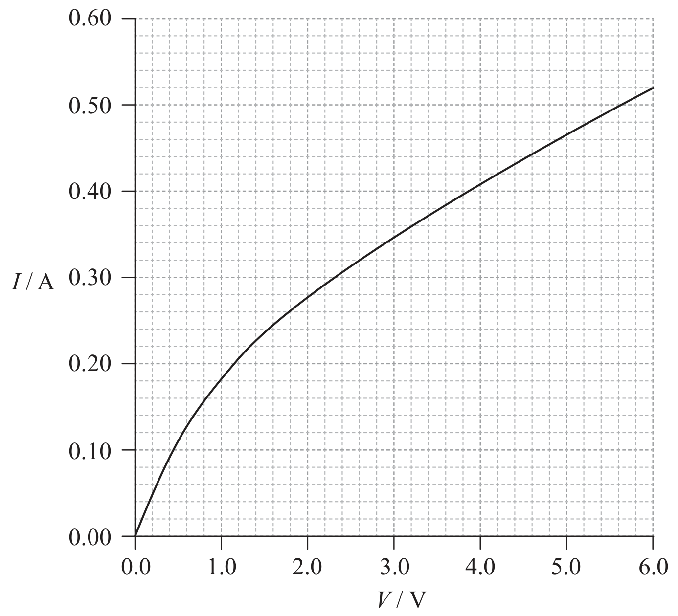
The graph below shows how the current I in a tungsten filament lamp varies with potential difference V across the lamp.

Figure for Question (a) — IB Physics SL
[ 10 ]

Question (i)

(i)

Define the electrical resistance of a component.

[ 1 ]

Question (ii)

(ii)

Explain whether or not the filament obeys Ohm's law.

[ 2 ]

Question (iii)

(iii)

Calculate the resistance of the filament lamp when the potential difference across it is 2.8 V .

[ 2 ]

Question (iv)

(iv)

The length of the filament in a lamp is 0.40 m . The resistivity of tungsten when the potential difference across it is 2.8 V is 5.8×10⁷Ω m5.8 \times 10^{-7} \Omega \mathrm{~m}. Calculate the radius of the filament.

[ 3 ]

Question (v)

(v)

Two identical filament lamps are connected in series with a cell of emf 6.0 V and negligible internal resistance. Using the graph on page 26, calculate the total power dissipated in the circuit.

[ 2 ]
All question bank results loaded