IB Physics SL B.5.15 Variable Resistance

Practise interpreting potentiometers, thermistors, light-dependent resistors and rheostats, using their changing resistance to predict current, voltage or measurement sensitivity.

Syllabus
First assessment 2025
Objective
Level
SL

Exam points

  • use a variable resistor to collect V-I points and find resistance or internal resistance from a graph gradient
  • predict current or divider output when thermistor or LDR resistance changes with temperature or light
  • read a resistance-response graph to identify the range with greatest sensitivity

B.5.15—Variable resistance question 1

[Maximum number: 3]

This question is in two parts. Part 1 is about a thermistor circuit. Part 2 is about vibrations and waves.
Part 1 Thermistor circuit
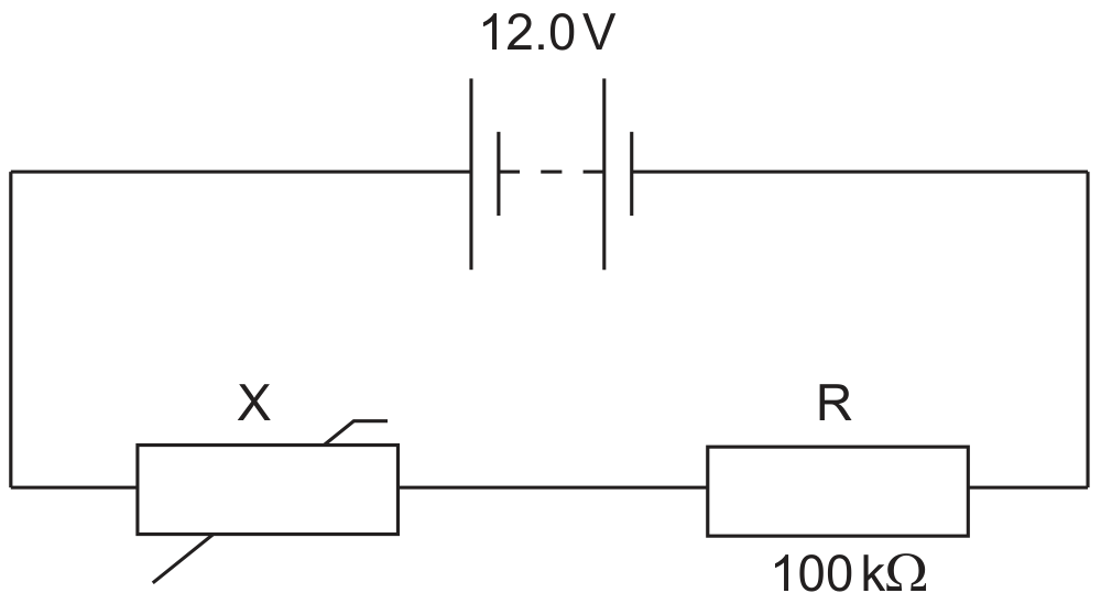
The circuit shows a negative temperature coefficient (NTC) thermistor X and a 100kΩ100 \mathrm{k} \Omega fixed resistor R connected across a battery.

Figure for Question B.5.15—Variable resistance question 1 — IB Physics SL

The battery has an electromotive force (emf) of 12.0 V and negligible internal resistance.

Question (a)

(a)

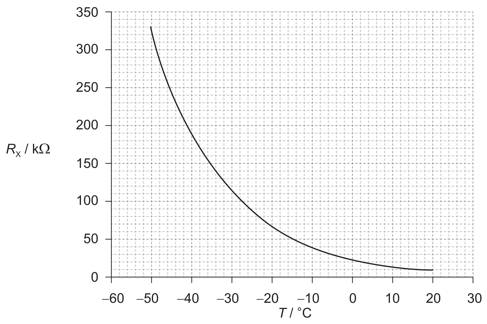
The graph below shows the variation with temperature T of the resistance RxR_{\mathrm{x}} of the thermistor.

Figure for Question (a) — IB Physics SL
[ 3 ]

Question (i)

(i)

State the range of temperatures for which the change in the resistance of the thermistor is most sensitive to changes in temperature.

[ 1 ]

Question (ii)

(ii)

State and explain the effect of a decrease in temperature on the ratio

 voltage across X voltage across R\frac{\text { voltage across } \mathrm{X}}{\text { voltage across } \mathrm{R}}

Part 2 Vibrations and waves

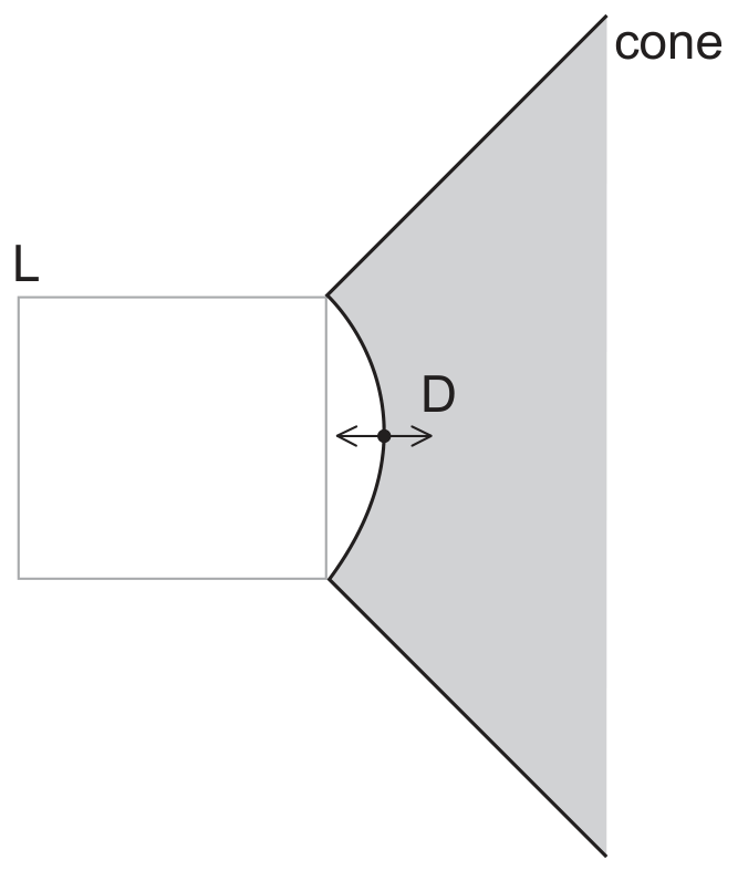
The cone and dust cap D of a loudspeaker L vibrates with a frequency of 1.25 kHz with simple harmonic motion (SHM).

Figure for Question (ii) — IB Physics SL
[ 2 ]
All question bank results loaded