EduNinja

IGCSE Physics(d) Electromagnetic inductionTopic Practice

(d) Electromagnetic induction

Edexcel IGCSE Physics (d) Electromagnetic induction question practice helps you revise this syllabus point with the course map in view. Use this page to focus on one topic, check the style of questions available, and connect each attempt back to the knowledge area it is testing.

EduNinja keeps Physics practice aligned to Edexcel, so you can move from topic review into exam-style question bank work without losing the syllabus structure. Start with a small set, mark the weak steps, then return to nearby topic links when a definition, graph, calculation, or explanation needs repair.

Question 2

[Maximum number: 3]

Diagram 1 shows the magnetic field between the poles of two strong bar magnets.
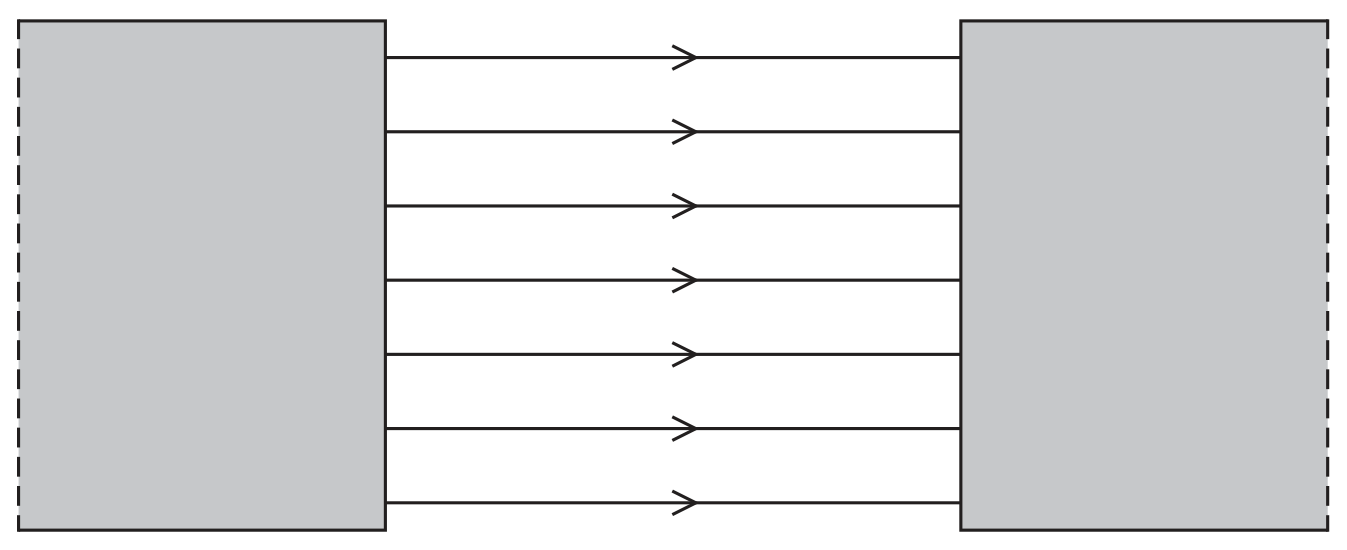
Diagram 1

Diagram 1

Question 2(d)

(a)

Diagram 2 shows a metal wire being moved downwards through the uniform field between the poles of the same bar magnets. The orientation of the magnets has not been changed.
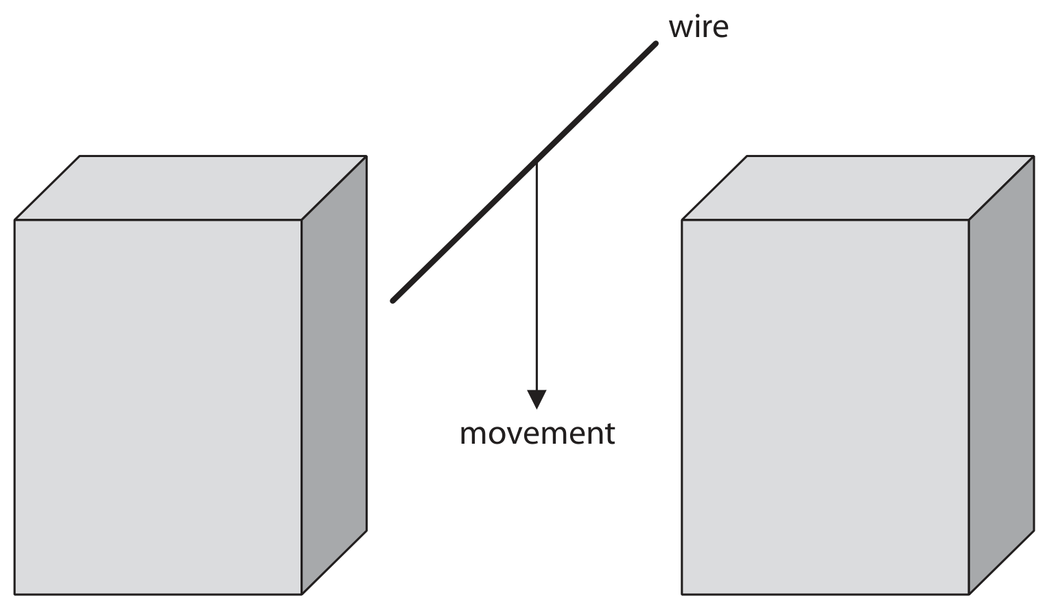
Diagram 2

Diagram 2

[ 3 ]

Question 2(d)(i)

(i)

Give a reason why a voltage is induced between the ends of the metal wire as it moves between the poles of the bar magnets.

[ 1 ]

Question 2(d)(ii)

(ii)

State two changes that could be made to this arrangement that would increase the magnitude of the induced voltage.

1

2

[ 2 ]
Question 2

[Maximum number: 7]

A student investigates a transformer.
This is the student's method.
- use a primary coil with 10 turns
- connect the primary coil to a constant maximum input voltage
- measure the output voltage across the secondary coil
- repeat using an increasing number of turns on the primary coil

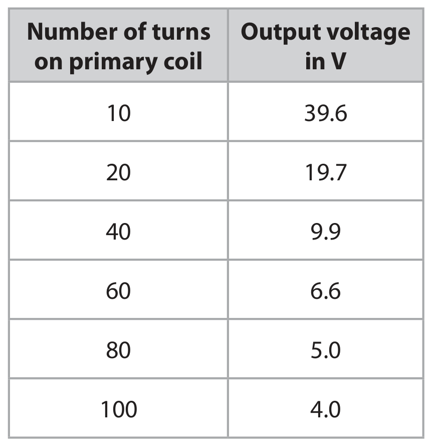
The table shows the student's results.

Table

Question 2(a)(i)

(a)

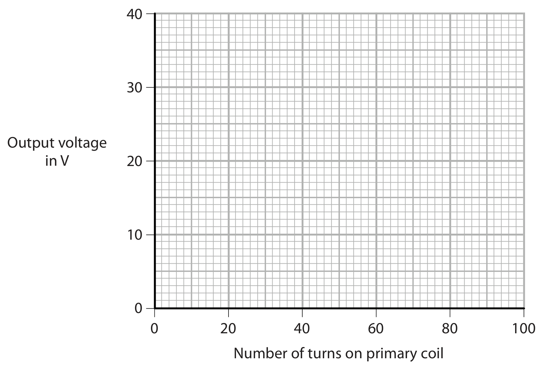
Plot a graph of the student's results on the grid.

[ 1 ]

Question 2(a)(ii)

(b)

Draw a curve of best fit.

Question image
[ 1 ]

Question 2(a)(iii)

(c)

Describe the relationship between the output voltage and the number of turns on the primary coil.

[ 2 ]

Question 2(b)(i)

(d)

State the formula linking input and output voltages and the turns ratio for the transformer.

[ 1 ]

Question 2(b)(ii)

(e)

The input voltage of the transformer is 6.8 V .

Calculate the number of turns on the secondary coil.
number of turns =

[ 2 ]

Question 4

[Maximum number: 6]

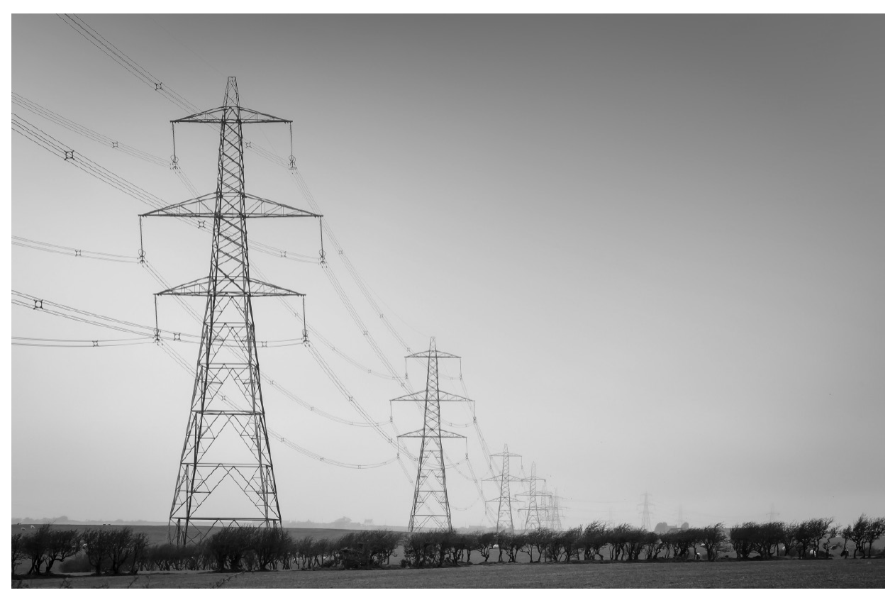
The photograph shows transmission cables used for long-distance transmission of electricity.

Question image

(Source: © Paul Maguire / Shutterstock)

Question 4(a)

(a)

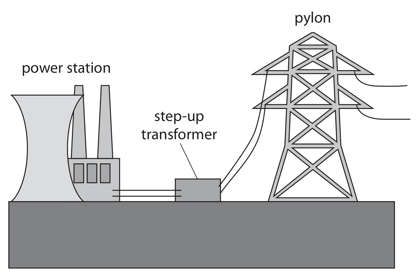
The diagram shows a power station and a school.

Add to the diagram by drawing the structures needed to efficiently transfer energy from the power station to the school using electricity.

Power station
School

Question image
[ 3 ]

Question 4(b)

(b)

Explain how the amount of current in the transmission cables increases the efficiency of the transmission of electricity.

[ 3 ]

Question 3

[Maximum number: 7]

Mobile phone charger X contains a transformer and is used to charge the phone's battery.

Diagram 1 shows the information on charger X.

Input voltage = 230 V
Output voltage = 5.0 V
Output current = 1.2 A

Diagram 1

Question 3(a)(ii)

(a)

Calculate the input current to charger X.

Assume that charger X is 100% efficient.

input current = ............ A

[ 3 ]

Question 3(c)

(b)

Both chargers contain step-down transformers.

Explain how a step-down transformer works.
You may include a diagram to support your answer.

[ 4 ]

Question 4

[Maximum number: 7]

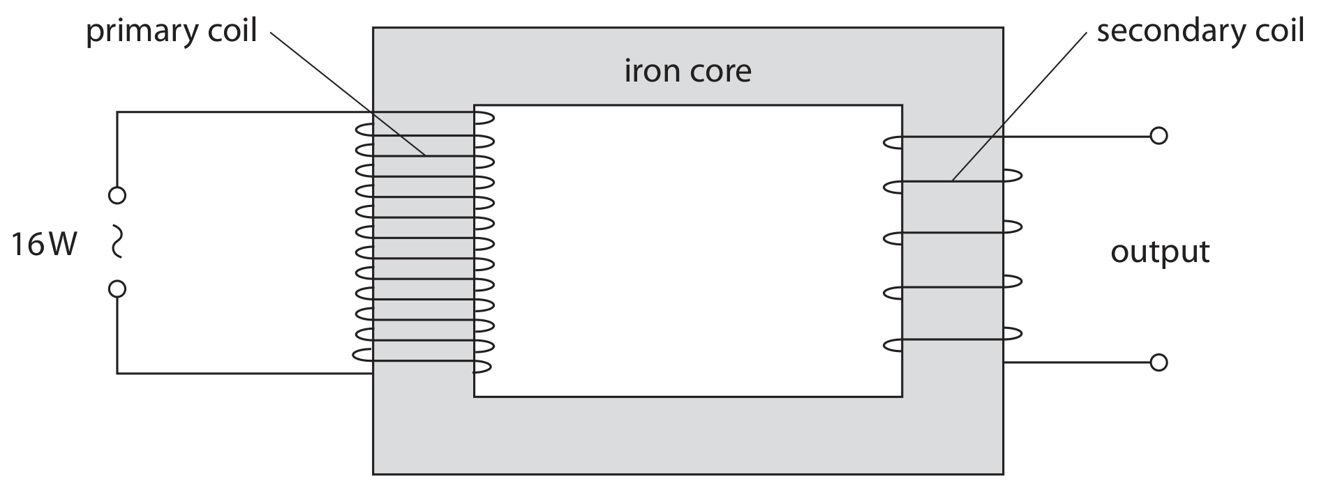
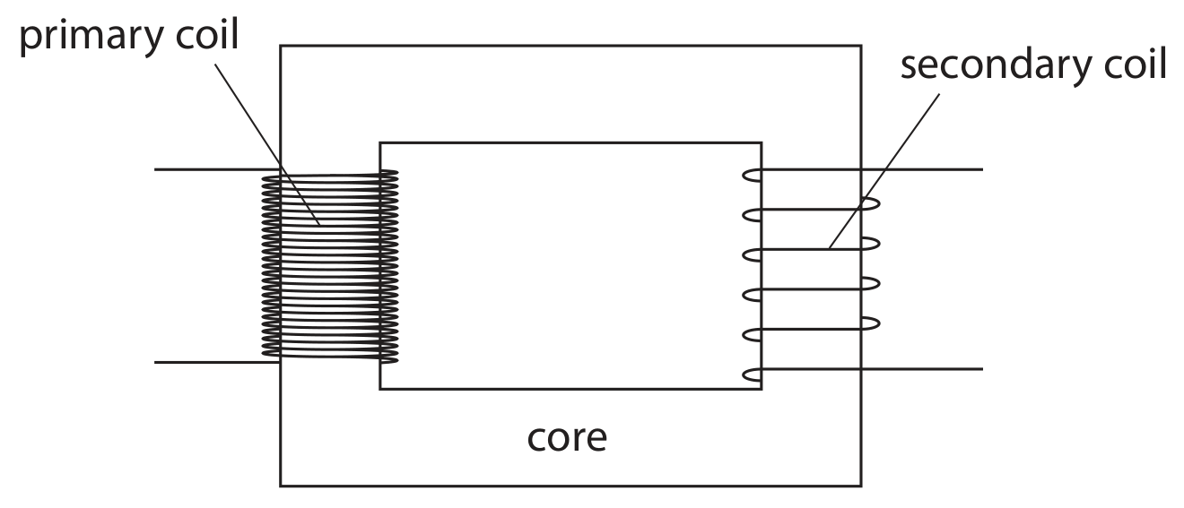
The diagram shows a step-down transformer.

Question image

Question 4(b)

(a)

Explain how a transformer works.

In your answer, include reasons for using
- two coils
- the iron core
- an a.c. power supply

[ 6 ]

Question 4(c)

(b)

State how the primary coil of the transformer can be changed to increase the output voltage.

[ 1 ]

Question 4

[Maximum number: 7]

This question is about transformers.

Question 4(a)

(a)

Describe the structure of a step-up transformer.

You may draw a diagram to help your answer.

[ 3 ]

Question 4(b)

(b)

A step-up transformer has an input voltage of 230 V and an input current of 4.5 A .

The output current of the transformer is 0.21 A .

[ 4 ]

Question 4(b)(i)

(i)

State the formula linking input power and output power for a transformer that is 100% efficient.

[ 1 ]

Question 4(b)(ii)

(ii)

Calculate the output voltage of the transformer.

output voltage = ............ V

[ 3 ]

Question 5

[Maximum number: 11]

The diagram shows part of the National Grid.

Question image

Question 5(a)

(a)

There is a step-up transformer at the power station end of a transmission line and a step-down transformer at a distant town.

Explain why step-up transformers and step-down transformers are used in this way.

[ 4 ]

Question 5(b)(i)

(b)

State the formula linking the input voltage, the output voltage and the turns ratio for a transformer.

[ 1 ]

Question 5(b)(ii)

(c)

The primary coil on a step-up transformer has 3300 turns.

Calculate the number of turns required on the transformer's secondary coil to step up the voltage from 15 kV to 340 kV.

number of turns = ............

[ 3 ]

Question 5(c)

(d)

Transformers in the National Grid have efficiencies less than 100%.

[ 3 ]

Question 5(c)(ii)

(i)

The iron core of a transformer is an electrical conductor.

When the transformer is in use, the primary coil causes a changing magnetic field in the iron core. This causes a small current to be induced in the core.

Explain how a current is induced in the core of the transformer.

[ 3 ]

Question 5

Question 5(b)

(a)

A transformer consists of two solenoids and an iron core.

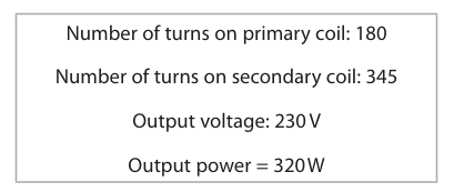
This is the label on the transformer.

Question image
[ 6 ]

Question 5(b)(i)

(i)

State the formula linking input (primary) voltage, output (secondary) voltage and the turns ratio.

[ 1 ]

Question 5(b)(ii)

(ii)

Calculate the input voltage of this transformer.

input voltage = ............ V

[ 3 ]

Question 5(b)(iii)

(iii)

Give the name of this type of transformer.

[ 1 ]

Question 5(b)(iv)

(iv)

When the transformer is in use, there is a current in the primary coil and in the secondary coil.

State the type of current in the coils of the transformer.

[ 1 ]

Question 6

[Maximum number: 7]

A student investigates transformers.

Question 6(a)

(a)

The diagram shows a typical transformer.

Question image

State the name given to this type of transformer.

[ 1 ]

Question 6(c)

(b)

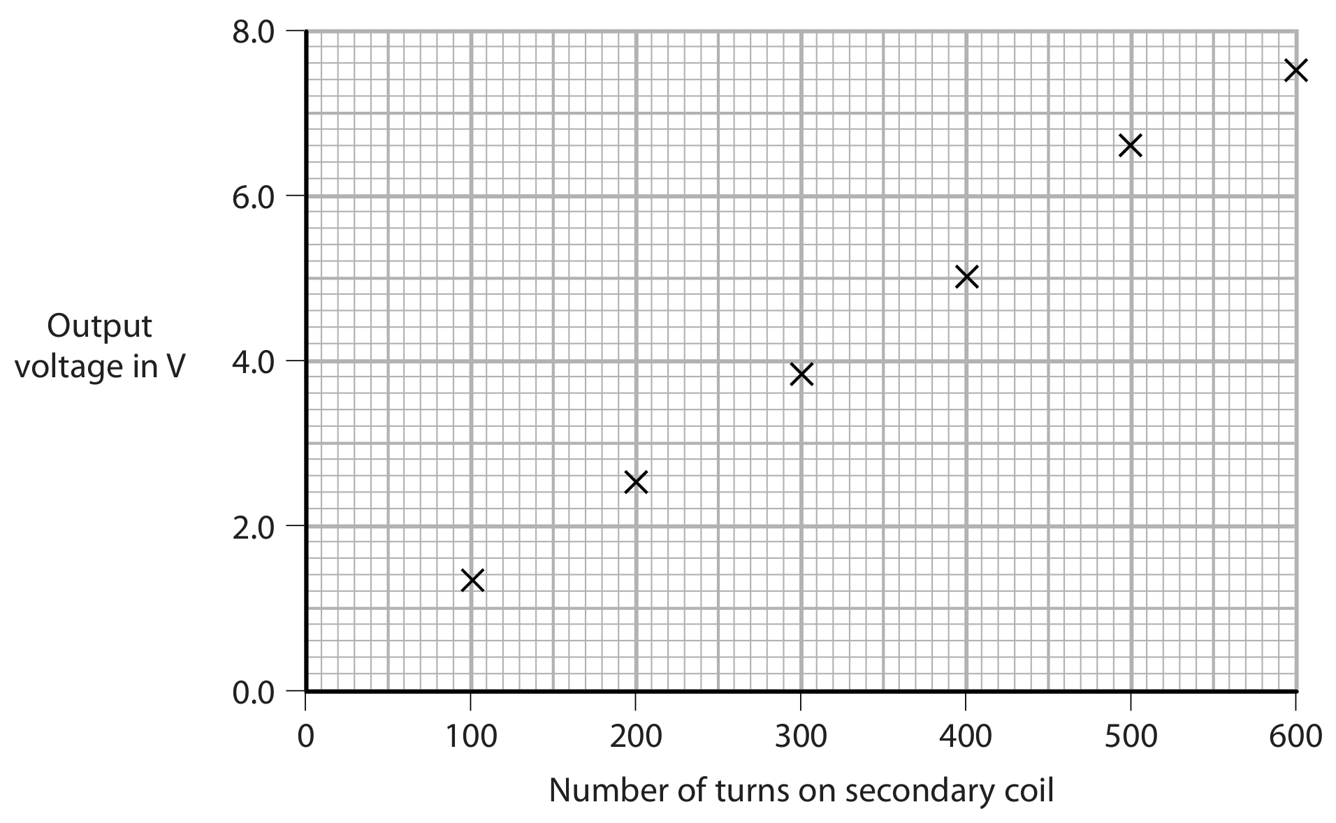
The student plots this graph to show the results of his investigation.

Question image
[ 2 ]

Question 6(c)(iii)

(i)

Describe the relationship shown by the graph.

[ 2 ]

Question 6(d)

(c)

The primary coil has 1200 turns.

Using the student's data, calculate the primary voltage used in his investigation.

primary voltage = ............ V

[ 4 ]

Question 5

[Maximum number: 9]

A transformer is used to charge a mobile phone.
The diagram shows a label on the transformer.
input voltage: 230 V
input current: 0.067 A
output voltage: 5.0 V
output current: 3.1 A

Question 5(a)

(a)

Explain how the information in the label shows that the transformer is a step-down transformer.

[ 2 ]

Question 5(b)

(b)

Show that the transformer is approximately 100% efficient.

[ 3 ]

Question 5(c)(i)

(c)

State the formula linking input voltage, output voltage and turns ratio for a transformer.

[ 1 ]

Question 5(c)(ii)

(d)

The primary coil has 1500 turns.

Calculate the number of turns on the secondary coil.

turns on secondary coil = ............

[ 3 ]
0 selected