Question 1
A student designs a circuit to turn on a fan when the temperature increases.
Which component does the student need to use in her circuit?
A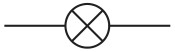
B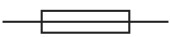
C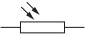
D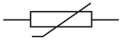
A student designs a circuit to turn on a fan when the temperature increases.
Which component does the student need to use in her circuit?
Fig. 6.1 shows the circuit diagram for a flashlight (torch).
Fig. 6.1
The electromotive force (e.m.f.) of the battery is 4.5 V . The circuit contains a fixed resistor. The current in the light-emitting diode (LED) is 0.020 A .
Explain why the LED does not light up if the battery is reversed.
Fig. 8.1 shows a circuit. The circuit is designed to switch on a night light when the surroundings are dark.
Fig. 8.1
On Fig. 8.1, draw the circuit symbol for a voltmeter used to measure the potential difference (p.d.) across the light-dependent resistor (LDR).