Question 28
[Maximum number: 1]
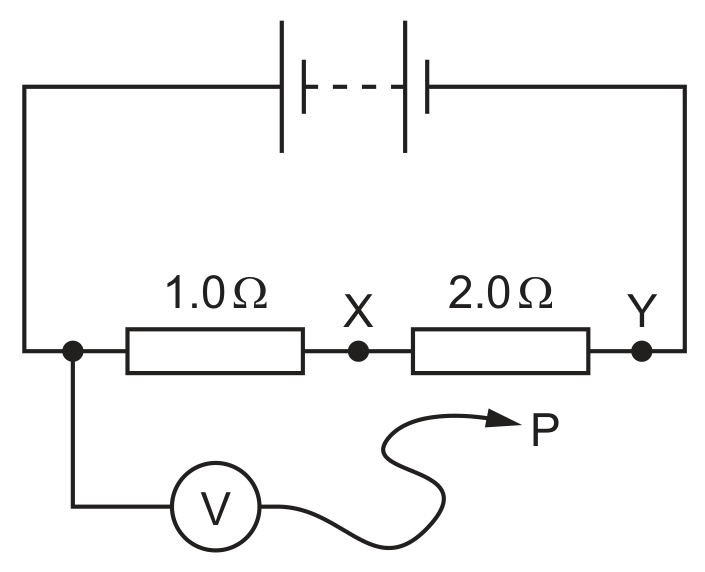
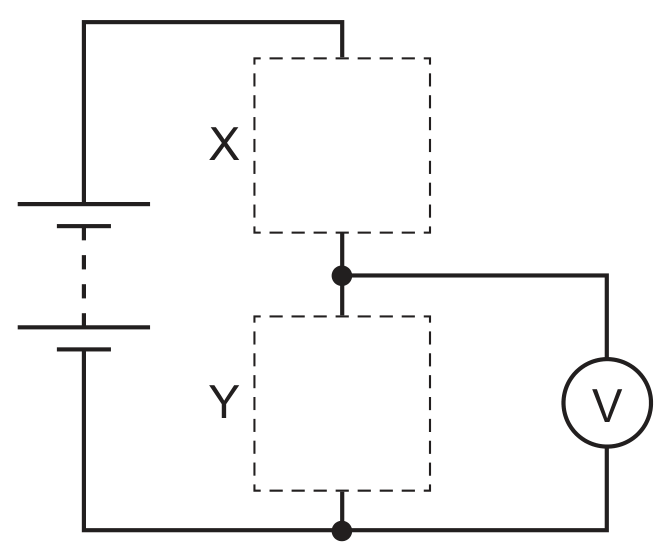
The diagram shows a circuit containing two resistors of resistance and .
A voltmeter is connected across the resistor by connecting P to X .
The reading on the voltmeter is 6.0 V .

P is moved to point Y in the circuit.
What is the new reading on the voltmeter?
A
B
6.0 V
C
12 V
D
18 V