Question 30
[Maximum number: 1]
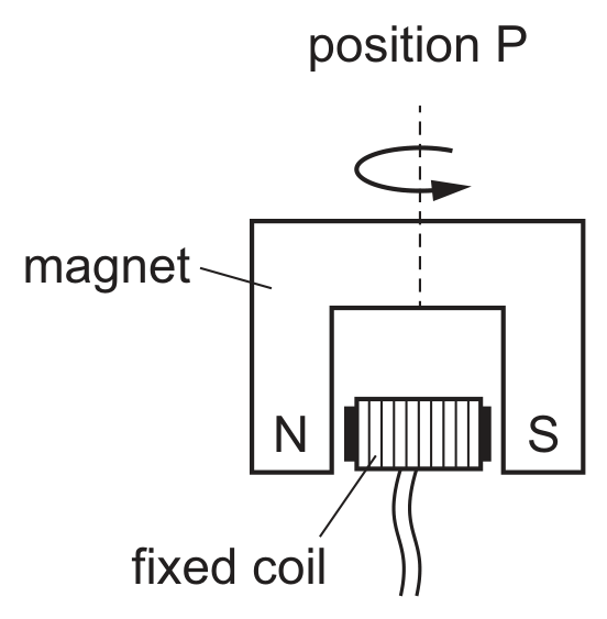
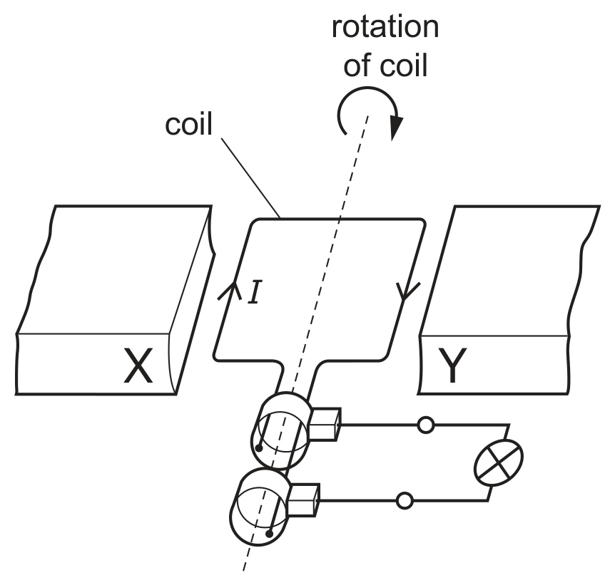
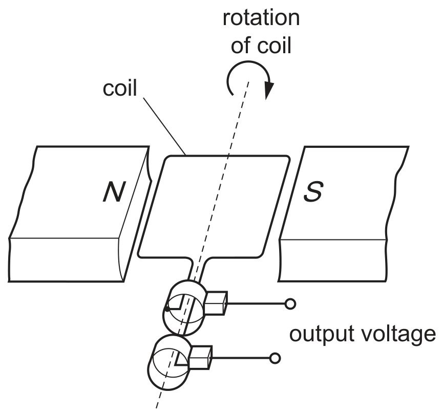
The diagram shows an a.c. generator.
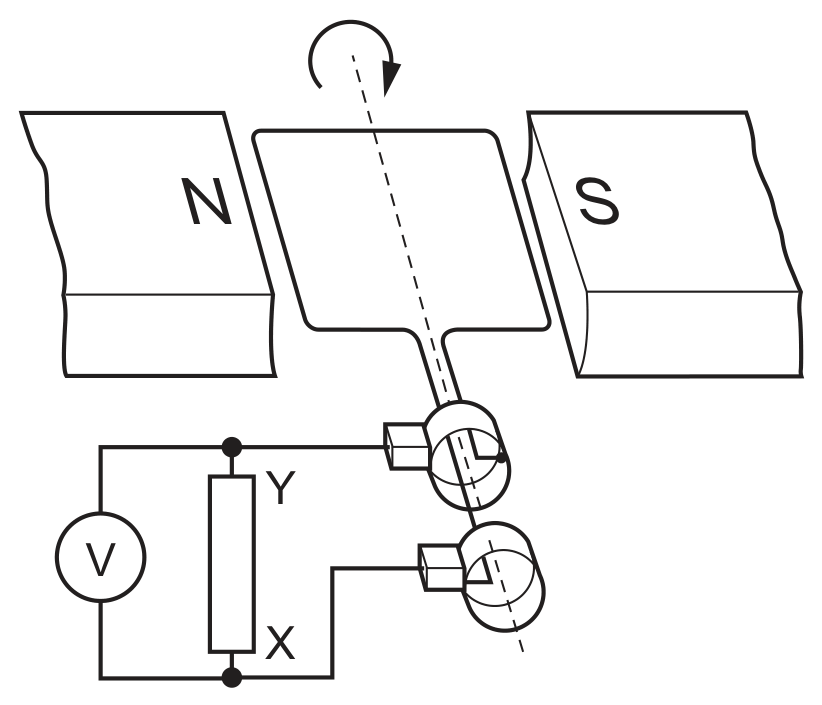
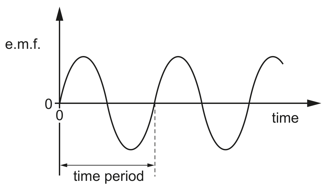
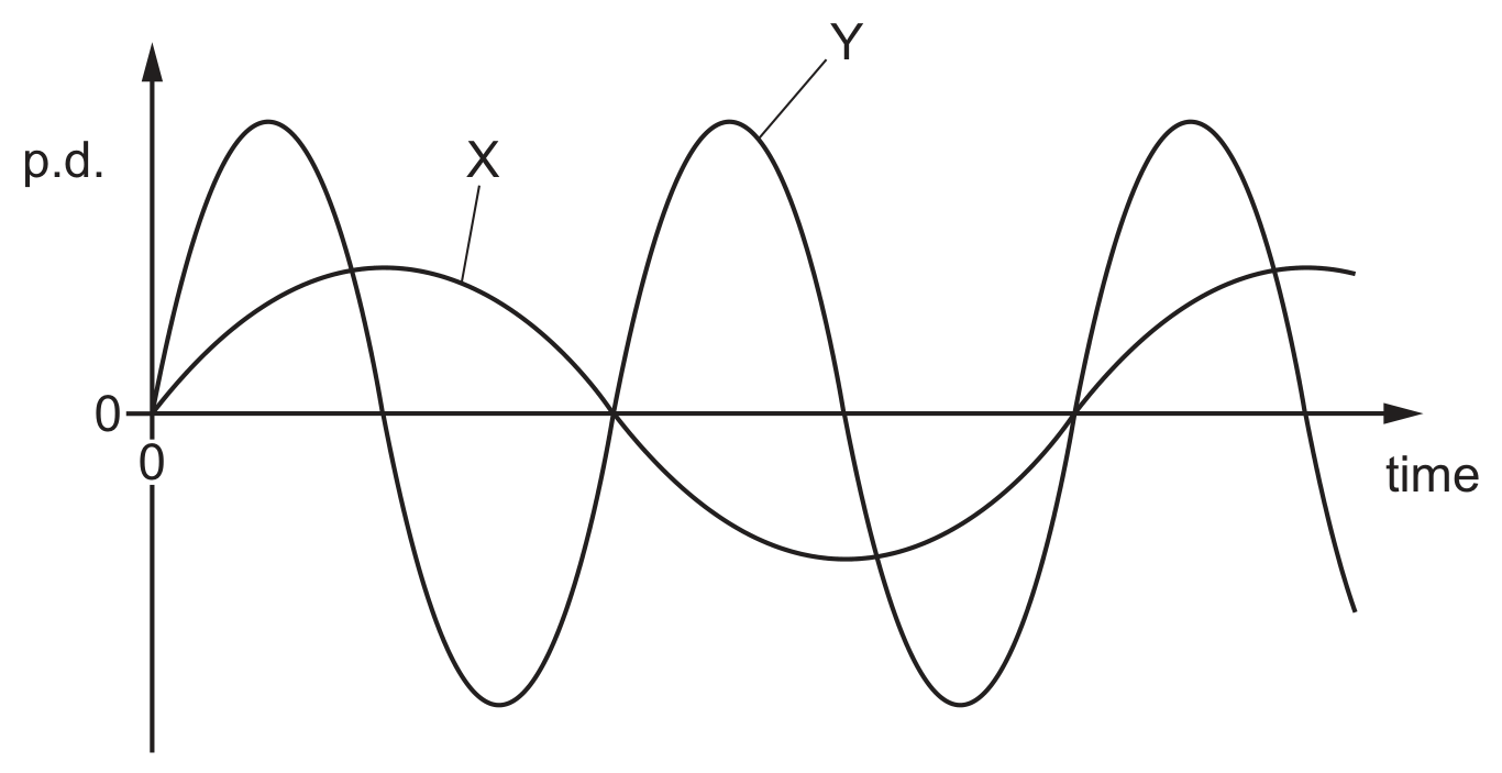
The graph shows the potential difference (p.d.) between points X and Y plotted against time. A positive value of p.d. indicates that X is more positive than Y.
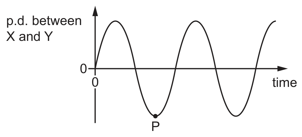
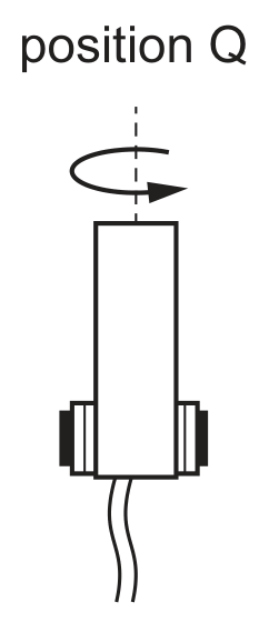
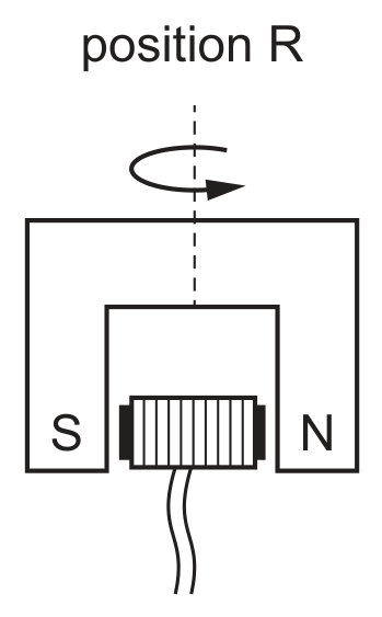
Which diagram shows the position of the coil at point P on the graph?